SERIES REVERSO HW KARTA KATALOGOWA DATASHEET
Udostępnij przez Social Media
Link do udostępniania
Użyj stałego linku do udostępniania w mediach społecznościowychWyślij do znajomego
Proszę login do wysłania tego document przez email!
Umieść na swojej stronie
38. 38
40. 40
42. 42
48. 48
30. 30
32. 32
31. 31
39. 39
41. 41
29. 29 Termostato remoto da posizionare a muro - Using a remote thermostat o be positioned on the wa ll - Verwenden Sie einen Fernthermostat - À l’aide d’un thermostat à distance, placez-vous su r le mur - Utilice un termostato remoto para colocarlo en la p ared
33. 33 Settaggi dip switch per giri motore – Dip switch setting for RPM - DIP-Schalter für RPM - Réglage du commutateur DIP pour RPM - Ajuste del interruptor DIP para RPM
4. 4 Wir gratulieren Ihnen zur Wahl eines Gebläsekonvekt ors REVERSO. Das vorliegende Handbuch enthält die für Transport, Installation, Bedienung und Wartung der Einheiten erforderlichen Informationen. Die Missachtung der Anleitungen bzw. eine unsachgemäße Installation der Geräte können z um Verfall der vom Hersteller geleisteten Garantie führen. Der Herstel ler haftet nicht für eventuelle direkte bzw. indire kte Schäden infolge falscher Installationen bzw. für Schäden, die durch Einheite n verursacht werden, die von unerfahrenem oder unbe fugtem Personal installiert wurden. Bei Empfang des Geräts kontrollieren Sie, ob es unv ersehrt und vollständig ist. Eventuelle Beanstandun gen müssen innerhalb 8 Tagen nach Erhalt der Ware schriftlich gemeldet wer den. Die Klimakonvektoren sind für den Einbau in Büro: u nd Wohnräumen . Die Klimakonvektoren sind ausschließlich zum Lufter wärmen, Filtern, Kühlen und Entfeuchten ausgelegt. Jeder andere Gebrauch ist ungeeignet. Klimakonvektor darf nicht eingesetzt werden für: : die Aufbereitung der Luft im Freien : die Installation in feuchten sehr Räumen : die Installation in explosiver Atmosphäre : die Installation in korrosiver Atmosphäre Überprüfen, dass der Raum, in dem das Gerät install iert wird, keine Stoffe enthält, die einen Korrosio nsprozess der Aluminium: rippen bewirken und die Metallstruktur. Je nachdem, ob der Raum beheizt oder gekühlt werden soll, werden die Geräte mit warmem, bzw. kalten Wasser gespeist. Dieses Gerät ist nicht dafür bestimmt,durch Persone n (einschließlich Kinder),mit eingeschränkten physi schen, sensorischen oder geistigen Fähigkeitenoder mangels Erfahrung und/oder mangels Wissen benutzt zu werde n, es sei denn sie werden durch eine für ihre Sicherhe it zuständige Person beaufsichtigt oder erhielten v on ihr Anweisungen, wie das Gerät zu benutzen ist. Kinder sollten beaufsichtigt werden, um sicherzuste llen, dass sie nicht mit dem Gerät spielen. Der Hersteller/Händler haftet nicht für eventuelle Leckagen oder Schäden, die durch die fehlerhafte In stallation, falschen Gebrauch oder Wartung der Klimakonvektoren die Nich teinhaltung der in diesem Benutzerhandbuch enthalte nen Anweisungen oder Vernachlässigung der erforderliche n Inspektionen,Reparaturen und Wartungsarbeiten entstehen.Diese Betriebsanleitung ist wesent:licher Bestandteil des Gerätes und muss folglich immer zu sammen mit diesem verwahrt werde Die Reverso-Serie ist CE-LVD-EMC-zertifiziert von S GS-Labors. Nous vous félicitons d’avoir choisi un ventilo:conv ecteur REVERSO. Le présent manuel fournit des instructions importan tes concernant le transport, l'installation, l'util isation et l'entretien des unités. Le non:respect de ces instructions comporte de plei n droit l'annulation de la garantie du constructeur . En outre, la responsabilité du constructeur est dégagée pour tous dommages dire cts et/ou indirects résultant d'erreurs dans l'inst allation et l'utilisation et/ou pour tous dommages résultant d'unités installées pa r un personnel non qualifié et non habilités à réal iser ces travaux. Au moment de la réception, s'assurer que l'unité es t complète, en bon état et répondant a la commande. Toutes réclamations devront être notifiées par écrit dans un délai maxi mum de 8 jours après réception de la marchandise. Les ventilo:convecteurs sont construits exclusivem ent pour le refroidissement, la filtration, le refroidissement et la déshumidifi:cation; ils ne so nt adaptés à aucun autre usage. Le ventilo:convecteur ne peut pas: : pour le traitement de l’air en plein air : être installé dans des locaux très humides : être installé dans des atmosphères explosives : être installé dans des atmosphères corrosives Vérifier que la pièce dans laquelle l’appareil est installé ne contient pas de substances pouvant en:g endrer la corrosion des ailettes en aluminium et la structure métallique. Les appareils sont alimentés avec de l’eau chaude/f roide selon qu’on veut chauffer ou rafraîchir la pi èce. L’appareil n’est pas prévu pour être utilisé par de s personnes (y compris les enfants) dont les capaci tés physi:ques, sensorielles ou mentales sont réduites, ou dénuées d’expérience ou de connaissance, sauf si elles ont pu bénéficier, par l’intermédiaire d’une person ne responsable de leur sécurité, d’une surveillance ou d’instructions préalables concernant l’utilisation de l’appareil.Il convient de surveiller les enfants pour s’assurer qu’ils ne jouent pas avec l’appareil.Le constructeur/vendeur décline tou te responsabilité en cas de fuites ou de dommages r ésultant d’une installation, un fonctionnement ou un entretien inc orrects des ventilo:convecteurs ou dus au non:respect des instructions de ce Livret de l’util isateur ou si les inspections, réparations et entre tiens nécessaires ne sont pas effectués.Ce livret doit to ujours accompagner l’appareil car il fait partie in tégrante de celui:ci. La série Reverso est certifiée CE - LVD -EMC par le s laboratoires SGS
5. 5 Congratulaciones por elegir un ventilconvector REV ERSO. Este manual presenta todas las informaciones utiles para el transporte, instalacion, uso y manutencion de las unidades. De no seguirse las instrucciones aqui descritas y/o en caso de una inadecuada instalacion de las unida des, el fabricante se reserva el derecho de anular la garantia. Tampoco l a empresa constructora responderà por eventuales da nos directos y/o indirectos provocados por instalaciones erroneas, y /o danos causados por unidades instaladas por perso nal inexperto o n o autorizado. Antes de proceder a instalar la maquina es necesari o comprobar que la unidad recibida estè completa y en perfectas condiciones. Las eventuales reclamaciones se deben presentar por escrito antes de que transcurran 8 dias de la rece pcion de la mercancia. Los ventiladores convectores han sido diseñados pa ra usarlos en locales comerciales y privados . Los ventiladores convectores han sido construidos e xclusivamente para las funciones de calefacción, filtrado, enfriamiento y deshumidi:ficación; no son adecuados paraningún otro uso. Los ventiladores convectores no se pueden usar para : : el tratamiento del aire al aire libre : su instalación en locales mucho húmedos : su instalación en atmósferas explosivas : su instalación en atmósferas corrosivas Compruebe que la estancia en la que se está instala do el aparato no contenga sustancias que generen un proceso de corrosión de las aletas de al uminio y la estructura de metal Los aparatos se alimentan con agua caliente/fría se gún si se desea ca:lentar o refrescar el local. Este aparato no debe ser utilizado por personas (in cluidos niños) cuyas capacidades físicas, sensorial es o mentales estén disminuidas o que carezcan de experi encia y conoci:mientos, al no ser que ellas hayan podido beneficiar, a través de la intermediación de una persona responsable de su seguridad, de una vigilancia o de instrucciones relativas al uso del aparato. Los niños han de vigilarse para asegurarse de que n o jueguen con el aparato. El fabricante/vendedor no puede considerarse respon sable de posibles pérdidas o daños debidos a la ins ta:lación, funcionamiento o mantenimiento incorrectos de los ventiladores con vectores o debidos al incumplimiento de las instrucciones del presente Ma nual de instruccio:nes para el usuario o si no se r ealizan las inspecciones, reparaciones y mantenimiento necesarios. Este manual debe acompañar siempre al aparato ya qu e forma parte del mismo. La serie Reverso está certificada CE - LVD-EMC por los laboratorios SGS.
44. 44 RDPK: Discharging Pump.
3. 3 1. PREMESSA - INSTRUCTION - EINFÜHRUNG – INTRODUCTION - INTRODUCCIÓN Congratulazioni per aver scelto un ventilconvettore REVERSO. La non osservanza di quanto qui descritto e/o una i nadeguata installazione delle macchine, possono ann ullare la garanzia. Il costruttore, inoltre, non risponde di eventuali dan ni diretti e/o indiretti dovuti ad errate installaz ioni, e/o danni causati dalle unità installate da personale inesperto o non autorizzato . Verificare, che la macchina ricevuta sia integra e completa e conforme all’ordine. Eventuali reclami d evono essere presentati per iscritto entro 8 giorni dal ricevimento della merce . I ventilconvettori sono destinati all’uso in ambie nti commerciali e privati. Essi sono costruiti es clusivamente per le funzioni di riscaldamento, filtrazione, raffreddamento e deumid ificazione; non sono adatti per nessun altro uso. Il ventilconvettore non può essere impiegato: :per il trattamento dell’aria all’aperto; :per l’installazione in ambienti estremamente umid i; :per l’installazione in atmosfere esplosive; :per l’installazione in atmosfere corrosive . Verificare inoltre che l’ambiente in cui è installa to l’apparecchio non contenga sostanze che generino un processo di corrosione delle alette in alluminio ,e della struttura metall ica. L’apparecchio non è destinato ad essere usato da pe rsone (bambini compresi) le cui capacità fisiche, s ensoriali o mentali siano ridotte, oppure con mancanza di esperienza o di con oscenza, a meno che esse abbiano potuto beneficiare , attraverso l’intermediazione di una persona responsabile della loro sicurezza, di una sorveglianza o di istruzion i riguardanti l’uso dell’apparecchio. I bambini devono essere sorvegliati per sincerarsi che non giochino con l’apparecchio. Il costruttore/venditore non può essere considerato responsabile di eventuali perdite o danni dovuti a installazione, funzionamento o manutenzione non corretti dei venti lconvettori o dovuti alla mancanza di conformità c on le istruzioni del presente Manuale di uso e installazione per l’utent e o qualora non vengano effettuate le ispezioni, ri parazioni e manutenzioni necessarie. Questo libretto deve accompagnare sempre l’apparecc hio in quanto parte integrante dello stesso. La serie Reverso è certificata CE - LVD -EMC presso i laboratori SGS Congratulations for choosing a fancoil REVERSO. This manual contains important information for the transportation, installation, use and maintenance o f units. Failure to follow the instructions given in this manual and/or unprofessi onal installation may invalidate the warranty. The manufacture cannot be responsible for any direct or indirect damages rela ted to units installed by unskilled or unauthorised persons. At the time of delivery check that the appliance is in perfect condition, complete in all parts and re sponding to your order. Any claims must be submitted in writing no later than 8 days after the date of delivery. The fan:coil units are exclusively built for air he ating, filtering, cooling and dehumidification. They are not suitable for any other purpose. The fan:coil unit may not be used: :for outdoor air treatment : for installation in too much moist rooms : for installation in explosive atmospheres : for installation in corrosive atmospheres Make sure that the environment where the appliance is installed does not contain substances that cause the corrosion of the aluminium fins , and the metal frame. The appliances are supplied with hot/cold water dep ending on whether the environment is being heated/c ooled. This appliace is not intended for use by persons (i ncluding children) with reduced physical, sensory o r mental capabilities, or lack of experience and knowledge, unless they have been given supervision or instruct ion concerning use of the appliance by a person respons ible for their safety. Children should be supervised to ensure that they d o not play with the appliance. The manufacturer/seller cannot be held liable for a ny loss or damage caused as a result of incorrect i nstallation, operation or maintenance of the fan coil units or due to any non :compliance with this User Information Manual or an y inspection, repair and maintenance requirement. This booklet must always accompany the appliance, b eing considered an integral part of such. Reverso series is CE - LVD -EMC certified by SGS la boratories.
18. 18 POSIZIONAMENTO DELL’UNITÀ - POSITIONING OF THE UNIT - POSITIONIERUNG DER EINHEIT - EMPLACEMENT DE L'UNITE - POSICIONAMIENTO DE LA UNIDAD Posizionare l’unità su di una struttura idonea a sopportare il peso della macchina. Si consiglia di utilizzare sistemi antivibranti, tali da impedire la trasmissione delle vibrazioni alla struttura stessa. Rispettare gli spazi minimi indicati in figura per agevolare le manutenzioni ordinarie e straordinarie. Scegliere un posizionamento che non penalizzi lo scarico della condensa. Position the unit on a structure able to support its weight. We recommend the use of antivibration systems to prevent the transmission of vibration to the supporting structure. Observe the minimum clearances shown in the figure to facilitate routine and supplementary maintenance procedures. Choose a position that facilitates the drainage of condensate. Die Einheit muss auf einer Struktur aufgestellt wer den, die in der Lage ist, das Gewicht des Geräts zu tragen. Es empfiehlt sich die Verwendung von schwingungsdämpfe nden Systemen, die die Übertragung der Vibrationen an die Struktur verhindern. Um die ordentlichen und außerordentlichen Wartungse ingriffe zu erleichtern, müssen die auf der Abbildu ng dargestellten Mindestfreiräume beachtet werden. Bei der Wahl des Standorts muss darauf geachtet wer den, dass der Kondensatablass nicht behindert wird. Positionner l'unité sur une structure apte à suppor ter le poids de l'appareil. Il est conseillé d'util iser des systèmes antivibratiles pour éviter la transmission des vibr ations à la structure elle:même. Respecter les espaces minimums indiqués en figure p our faciliter les opérations d'entretien courant et extraordinaire. Choisir un emplacement qui ne pénalise pas l'évacua tion des condensats. La unidad se debe emplazar sobre una estructura apr opiada para soportar el peso de la maquina. Es aco nsejable usar sistemas antivibracion de manera que se impida la trasmision de las vibraciones. Es necesario seguir al pie de la letra los espacios minimos mostrados en la figura con el fin de facil itar la manutencion ordinaria y extraordinaria. Tambien se debe elegir una posicion que permita el drenaje de la condensacion.
21. 21 ACCESSO ALLA SCHEDA ELETTRONICA. ACCESS TO MAIN ELECTRONIC BOARD. ZUGANG ZUM HAUPTELEKTRONIKPLATZ ACCÈS AU PANNEAU ÉLECTRONIQUE PRINCIPAL ACCESO A LA JUNTA ELECTRONICA PRINCIPAL. Per accedere alla scheda elettronica, rimuovere le due viti indicate nell’immagine a sinistra. To access to main PCB, remove the two screws shown in the picture on the left Um auf die Hauptplatine zuzugreifen, entfernen Sie die beiden links abgebildeten Schrauben Pour accéder à la carte électronique principale, re tirez les deux vis indiquées dans l'image à gauche. Para acceder a la placa electrónica principal, reti re los dos tornillos que se muestran en la imagen de la izquie rda Per rimuovere la copertura e accedere alla scheda elettronica, alzare la stessa copertura come indica to dalla freccia nella figura alla destra. To remove the cover and access to main PCB, move up the same cover as shown in the picture on the left. Um die Abdeckung abzunehmen und auf die elektronisc he Hauptplatine zuzugreifen, schieben Sie dieselbe Abdeckung nach oben, wie in der Abbildung links gez eigt. Pour retirer le couvercle et accéder au tableau électronique principal, remontez le même couvercle, comme indiqué sur la photo à gauche. Para quitar la cubierta y acceder al tablero electr ónico principal, suba la misma cubierta como se muestra e n la imagen de la izquierda.
43. 43 V22RSHAMK 2/6 - V22RSHAMK 8 - V23RSHAMK 2/6 - V23RSHAMK 8 VALVOLA CON MICRO : VALVE WITH MICRO VERSION : VENTIL MIT MIKRO – VANNE AVEC MICRO : VÁLVULA CON MICRO
20. 20 RIMOZIONE DEI FIANCHI IN METALLO REMOVAL OF THE METAL FLANKS ENTFERNUNG VON METALLSEITEN ENLÈVEMENT DES CÔTÉS MÉTALLIQUES ELIMINACION DE LADOS METÁLICOS Rimuovere le due viti indicate relative al fianco destro. La stessa operazione va ripetuta per il fianco sinistro. Remove the two screws relative to right bracket. The same operation will make for the left flank. Entfernen Sie die beiden Schrauben relativ zur rechten Halterung. Dieselbe Operation wird für die linke Flanke ausgeführt. Retirez les deux vis par rapport au support droit. La même opération conduira au flanc gauche. Retire los dos tornillos en relación con el soporte derecho. La misma operación hará para el flanco izquierdo. Rimuovere le due viti indicate relative al fianco destro. La stessa operazione va ripetuta per il fianco sinistro. Remove the two screws relative to right bracket. The same operation will make for the left flank. Entfernen Sie die beiden Schrauben relativ zur rechten Halterung. Dieselbe Operation wird für die linke Flanke ausgeführt. Retirez les deux vis par rapport au support droit. La même opération conduira au flanc gauche. Retire los dos tornillos en relación con el soporte derecho. La misma operación hará para el flanco izquierdo. Procedere alla rimozione del fianco destro e sinistro come indicato nell’immagine alla sinistra. Remove the right and left metal flanks as indicated in the image on the left. Entfernen Sie die rechten und linken Metallflanken wie in der Abbildung links gezeigt. Retirez les flancs métalliques droit et gauche comme indiqué sur l'image à gauche. Retire los flancos metálicos derecho e izquierdo como se indica en la imagen de la izquierda.
37. 37 NOTA PER L’INSTALLAZ IONE DELLE VALVOLE. NOTE FOR ALL THE VAL VES INSTALLATION . HINWEIS FÜR ALLE VENTILINSTALLATIONEN. NOTE POUR TOUTE L'INSTALLATION DES VANNES. NOTA PARA TODAS LAS INSTALACIONES DE VÁLVULAS. Tutte le foto sotto riportate sono solo indi cative. All the below pictures are only indicative . Alle untenstehenden Bilder sind nur Richtwerte. Toutes les images ci:dessous ne sont qu'indicatives . Todas las imágenes a continuación son solo indic ativas. Si consiglia di rimuovere il pannello frontale frontale in corrispondenza del ventilatore e di far passare i c avi dell’attuatore/i come nella foto a sinistra It is recommended to remove the front front panel a t the fan and to pass the cables of the actuator / s as in the photo on the left. Es wird empfohlen, die vordere Frontplatte am Lüfte r zu entfernen und die Kabel des / der Stellantriebe (n) wie auf dem Foto links zu verlegen Il est recommandé de retirer le panneau avant avant du ventilateur et de faire passer le (s) câble (s) de l'actionneur comme sur la photo de gauche Se recomienda quitar el panel frontal frontal del ventilador y pasar los cables de los actuadores com o se muestra en la foto de la izquierda
17. 17 Unitè pour installation à l'interieur. Pour la manutention des unités, utiliser des appare ils ou engins de levage appropriés conformément aux dispositions de la directive 2007/30/CEE et modificatifs Le constructeur décline toute responsabilité en cas de non-respect des règles de sécurité et de préven tion suivantes. La responsabilité du constructeur est d'autre part dég agée pour tous dommages dérivant d'une utilisation inhabituelle des unités et/ou de toutes modifications ou réparations de str ucture sans autorisation préalable. L'installation doit être effectuée par un professio nnel qualifié. Le port d'EPI appropriés conformémen t à la directive 93/68/CEE et modificatifs, est obligatoire. Respecter la réglementation locale ou nationale en vigueur dans le pays d'installation de l'unité conc ernant l'utilisation et à l'élimination de l'emballage et des produits de nettoyage et d'entre tien de l'appareil. Avant de mettre en service l'unité, contrôler le pa rfait état des différents composants et de toute l' installation. Eviter impérativement de toucher des parties en mouvement. Avant d'entreprendre toute opération de nettoyage o u d'entretien, isoler l'appareil du réseau d'alimen tation électrique. Les pièces de rechange doivent se conformer aux exi gences définies par le constructeur. En cas de déma ntèlement des unités, respecter la législation antipollution en vigueur. L'installateur et l'utilisateur doivent tenir compt e et parer à tous les types de risques liés à l'uti lisation des unités dans leur propre installation. Par exemple, risques dus à la pénétration de corps étra ngers ou au transport de gaz toxiques ou inflammabl es dans les environnements thermorégulés. Unidad para instalacion al interno Para mover las unidades se deben usar medios apropi ados como se prevè en la directiva 2007/30/CEE y su cesivas modificaciones. El fabricante rehúsa cualquier responsabilidad por el incumplimie nto de las normas de seguridad y prevencion descrit as en el presente manual. Por otra parte rechaza cualquier responsabi lidad por los daños debidos a un uso inapropiado de las unidades y/o por modificaciones realizadas sin autorización. Solo personal especializado deberà proceder con la instalacion de las maquinas. Durante la instalacion se debe usar vestuario idóneo para evitar accidentes como indicado en la norma 93/68/CEE y su cesivas. Se deben respetar las leyes en vigor en el país en el cual se instala la máquina, relativas al uso y l a eliminación del embalaje y de los productos empleados para la limpieza y la manutención de la m áquina. Antes de poner en funcionamiento la unidad, se debe verificar la integridad de todos los componentes a si como la instalación completa. Evitar absolutamente el contacto fisico con las partes en movimiento. Es absolutamente imprescindible desenchufar las uni dades de la alimentacion electrica antes de procede r con las labores de manutención y de limpieza. Las piezas de repuesto usadas en las maquinas deben atenerse a las exigencias definidas por la empresa constructora. Para desmantelar las unidades es preciso observar las normas ambientales vigentes en cada pais. Tanto el instalador como el usuario deben tomar pre cauciones relativas a todos los demas riesgos asoci ados con el uso de las unidades en la propia instalación. De tal manera se deben tener en cuenta los potenciales peligros relativos al ingre so de cuerpos extraños o la entrada de gases tóxicos o inflamables en los ambientes tratad os. Nota: in assenza di valvole motorizzate di intercettazio ne acqua e in condizioni ambiente con alta percentu ale di umidità e bassa temperatura dell’acqua in batteria, il fancoil potrebbe creare condensa sulla struttura in metallo. Per questo mot ivo è necessario eseguire accurati controlli sulle condizioni di utilizzo e funzionamento (vedi diagra mma psicrometrico) e assicurarsi di poter fare a me no delle valvole sopraccitate. L’azienda non risponderà in alcun modo di danni cau sati dalla suddetta condensa. Notes: if no motor:driven water shutoff valve is present, and in environmental conditions with a high percen tage of humidity and low temperatures of the water in the coil, the fancoil may form cond ensate on the metal structure. For this reason, the conditions of use and operation must be checked thoroughly (see psychrometric diagram) and ensure that operation without the above valves is f easible. The company will not be liable under any circumstan ces for damage caused by the above condensation. Anmerkung: Wenn keine angetriebenen Wassersperrventile vorlie gen, bzw. bei Umgebungen mit einem hohen Feuchtigke itsgehalt und niedriger Wassertemperatur in der Batterie könnte der Fancoil Kondenswasser an der Metallstruktur verursachen. A us diesem Grund ist es notwendig, sorgfältige Kontrollen der Anwendungs: und Betriebs bedingungen auszuführen (siehe das psychrometrische Diagramm) und sicherstellen, ob die Abwesenheit der oben genannten Ventile möglich ist. Das Unternehmen haftet nicht für die durch dieses K ondenswasser hervorgerufenen Schäden. Remarque: en l’absence de vannes d’isolement motorisées de l ’eau et dans des conditions ambiantes présentant un pourcentage élevé d’humidité et une basse température de l’eau dans la batterie, le ventilo:convecteur pourrait générer des condens ats sur la structure en métal. C’est pourquoi il est nécessaire d’effectuer des contrôles méticuleux sur les conditions d’utilisation et de fonctionnem ent (voir diagramme psychrométrique) et de s’assurer que ces vannes ne sont pas indispensables . L’entreprise ne répondra en aucun cas des dommages causés par les éventuels condensats. Nota: faltando las válvulas motorizadas de cierre de agu a y en condiciones ambientales con un alto porcenta je de humedad y una baja temperatura del agua en la batería, el fancoil podr ía crear condensación sobre la estructura de metal. Por tal motivo es necesario llevar a cabo un control minucioso de las condiciones de uso y funci onamiento (véanse los diagramas psicrométricos) y c omprobar si es posible no utilizar las válvulas antedichas. La empresa no responderá de los daños causados por dicha condensación.
24. 24 COLLEGAMENTI IDRAULICI - HYDRAULIC CONNECTIONS -WASSERANSCHLÜSSE – CONNECTIONS HYDRAULIQUES - CONEXIONES HIDRÁULICAS Gli scambiatori delle unità sono forniti di attacch i filettati gas “femmina” (1/2” GF). La pressione m assima di esercizio delle batterie non deve superare i 6 bar Rispettare le indicazioni poste sul fianco delle un ità relative all’entrata e all’uscita dell’acqua ne lla batteria. Durante l’allacciamento degli apparecchi senza valv ole serrare i tubi con cautela per evitare possibil i danneggiamenti. Al termine delle suddette operazioni si raccomanda di controllare tutti i diversi raccordi e le guarni zioni di tenuta. Prevedere valvole di intercettazione per isolare la batteria dal resto del circuito in caso di manuten zione straordinaria. In caso di più fancoil collegati alla stessa tubazi one dell’acqua, procedere singolarmente all’apertur a delle corrispondenti valvole di intercettazione per poter identificare subito e fermare eventuali perdite idrauliche Nel caso di installazione in zone con climi partico larmente freddi, svuotare l’impianto in caso di lun ghi periodi di fermo:impianto. Prima di avviare l’impianto, controllare il regolar e reflusso della condensa raccolta nella vaschetta, se necessario dare una leggera pendenza verso lo scarico per favo rirne l’uscita. The unit's exchangers are equipped with female thre aded gas connectors (1/2” GF). The nominal pressure should not overtake 6 bar. Observe the indications stuck on the side of the un it giving the coil water inlet and outlet connectio ns. When connecting units without valves tight the pipe s carefully to avoid damage. When the above operations have been completed caref ully check all the junctions and sealing gaskets. Install shut:off valves to isolate the coil from th e circuit for supplementary maintenance requirement s. In the case of multiple fan coil connected to the s ame water pipe, proceed individually to the opening of the corresponding valves to be able to immediately identify and stop any water leaks In the case of installation in places with particul arly cold climates, empty the circuit prior to prol onged system shutdowns. Before start-up the system check the correct draina ge of the condensate from the drain pan. If needed give a slight inclination towards the discharge. Die Wärmetauscher der Einheit sind mit Schraubansch lüssen versehen (1/2“ GF). Der maximale Druck der B atterie darf 6 Bar nicht überschreiten. Was den Ein – und Austritt des Wassers in die Batte rie betrifft, sind die Hinweise seitlich an den Ein heiten zu beachten. Der Wärmeaustausch erfolgt im Gegenstrom. Nach Beendigung der obigen Arbeitsgänge kontrollier en Sie alle verschiedenen Anschlüsse und die Dichtu ngen. Bauen Sie Sperrventile ein, um das Register im Fall e von außerordentlichen Wartungseingriffen vom rest lichen Kreislauf isolieren zu können. Im Falle von mehreren Fan:Coil mit dem g leichen Wasserrohr, einzeln fahren Sie mit dem Öffn en der entsprechenden Ventile in der Lage sein, sofort identifizieren und zu stoppen keine Wasserlecks Bei Installation in besonders kalten Klimazonen mus s die Anlage bei längerem Stillstand entleert werde n. Vor dem Start der Anlage prüfen Sie den regulären R ückfluss des im Behälter gesammelten Kondenswassers . Wenn es notwendig ist, Schaffen Sie eine leichte Ne igung zum Auslass, um den Austritt zu begünstigen Les échangeurs des unités sont munis de raccords fi letés Gas femâle (1/2” GF). Respecter les indications inscrites sur le panneau latéral des unités concernant l'entrée et la sortie de l'eau dans la batterie. Lors du raccordement des appareils sans valves, ser rer les tubes avec précaution pour éviter tous dégâ ts. A’ la fin de ces opérations, il est recommandé de c ontrôler tous les raccords et les joints d'étanchéi té pour s'assurer que tout est en ordre. Prévoir des soupapes ou vannes d'arrêt pour isoler la batterie du reste du circuit en cas d'opérations d'entretien extraordinaire. Dans le cas des ventilo:convecteur multiple relié à la conduite d'eau même, procéder individuellement à l'ouverture des vannes correspondantes pour pouvoir identifier immédiateme nt et cesser toute fuite d'eau Dans le cas d'installation dans des zones à climats particulièrement froids, vidanger le circuit si l' appareil est destiné à rester inutilisé pour une longue période. Avant de commencer l'installation, vérifiez le refl ux régulier de condensat collecté dans le bac, le c as échéant donner une légère pente vers le drain pour facilite r la sortie. Las baterías de las unidades están provistas de con exiones roscados 1/2” GF. Se deben respetar las indicaciones incluidas al cos tado de las unidades, relativas a la entrada y sali da del agua en la batería. La presion maxima de la bateria no debe exceder los 6 bar. Al conectar los aparatos sin las valvulas se deben apretar con precaucion los tubos para evitar danos. Una vez terminadas las operaciones es recomendable verificar todas las conexiones y la hermeticidad de las juntas. Se recomienda situar válvulas de interceptación par a aislar la batería del resto del circuito en caso de que se deba efectuar una manutención extraordinaria. En el caso de múltiples unidades conectadas a la mi sma tubería de agua, proceder individualmente a la apertura de las válvulas correspondientes para ser capaz de identificar inme diatamente y detener cualquier fuga de agua En zonas con clima particularmente frio es indispen sable vaciar el circuito si el aparato permanecerá inutilizado por largo tiempo. Antes de cerrar la maquina chequear que la descarga de la condensaciòn funcione correctamente; si es n ecesario dar una ligera inclinación hacia el tubo de salida.
6. 6 IDENTIFICAZIONE UNITÀ - IDENTIFICATION OF THE UNIT - KENNDATEN DER EINHEIT - IDENTIFICATION DE L'UNITE- IDENTIFICACIÓN DE LA UNIDAD Le unità REVERSO sono dotate di una targhetta posta sul fianco della macchina che identifica: REVERSO units feature a dataplate located on one side of the appliance, showing: Seitlich von den Geräten der Einheit REVERSO befindet sich ein Typenschild mit folgenden Kenndaten: Sur chaque unité REVERSO est apposée une plaquette d'identification (autrement dit signalétique) sur le côté de l'unité portant les indications suivantes: Las unidades REVERSO poseen una tarjeta situada en el costado de la máquina que indica: Indirizzo del Costruttore Modello Codice Colore Tensione di alimentazione Potenza el. Assorbita Potenza frigorifera Potenza termica Portata aria Pressione sonora Peso netto Numero di matricola Marcatura CE Manufacturer's Address Model Code Colour Power supply voltage Unit power absorption Cooling capacity Heating capacity Air flow Sound pressure level Net weight Serial number CE Mark Anschrift des Herstellers Modell Code Farbe Anschlussspannung Motorleistung Kühlleistung Wärmeleistung Luftvolumenstrom Schalldruck GEWICHTE Seriennummer CE:Kennzeichnung Adresse du constructeur Modèle Code Couleur Tension d'alimentation Absorption Puissance frig Puissance thermique Débit d'air Pression acoustique POIDS Numéro de série Marquage CE Dirección del fabricante Modelo Código Color Tensión de alimentación Absorción Potencia frigorífica Potencia térmica Capacidad de aire Presión sonora PESOS Número de serie Marca CE 2. CARATTERISTICHE TECNICHE - TECHNICAL FEATURES -TECHNISCHE MERKMALE - CARACTERISTIQUES TECHNIQUES - CARACTERÍSTICAS TÉCNICAS La struttura della macchina è realizzata in lamiera zincata di spessore 0,8:1 mm. I filtri dell’aria sono di classe G1 e possono esse re agevolmente rimossi, per consentirne un’adeguata pulizia e manutenzione. L’isolamento acustico e termico della macchina è re alizzato in materiale CL1 – M1. La batteria di scambio termico è realizzata con tub i di rame e collettori in ottone, mandrinati su ale tte corrugate di alluminio. Gli attacchi hanno filettatura 1/2” Gas femmina. La bacinella di raccolta condensa è anch’essa in la miera zincata e verniciata, può essere rimossa dall a struttura. Deflettori e ventilatore in alluminio. The unit frame is made of 0,8:1 mm gauge metal shee t. Class G1 air filters designed for easy removal for trouble:free cleaning and maintenance purposes. Acoustic and thermal insulation is provided by CL1 – M1 material. The exchanger coil is composed of copper tubes and brass headers; the tubes are mechanically expanded into corrugated aluminium fin collars. Coil connectors with 1/2” Ga s female. Equipped with a removable galvanised steel condensa te drain pan. Swings and fan blower made in aluminum. Die Struktur der Maschine besteht aus 0,8:1 mm von starkem verzinktem Stahlblech. Die Luftfilter sind in Klasse G1 und können für ein e korrekte Reinigung und Wartung problemlos ausgeba ut werden. Die Schall: und Wärmeisolierung der Maschine besteh t aus CL1 – M1 Material. Der Wärmetauscher ist aus Kupfer und Messing Mannig faltigkeiten, die an gewellten Aluminiumrippen aufg edornt sind. Die Anschlüsse haben ½“ Gas Female:Außengewinde. Die Kondensatwanne ist ebenfalls aus lackiertem und verzinktem Blech oder, und kann herausgenommen wer den. Schaukeln und Gebläse aus Aluminium . La structure de la machine est réalisée en tôle d’a cier zinguée de 0,8:1 mm d’épaisseur. Les filtres à air sont de classe G1 sont démontable s pour faciliter leur entretien et nettoyage. L’isolation acoustique et thermique est réalisée en CL1 – M1 isolation . La batterie d’échange thermique est réalisée avec d es tubes cuivre et des collecteurs en Laiton sur de s ailettes d’aluminium pliées. Les raccords ont un filetage au pas du 1/2" GAS femelle. Le bac à condensas amovible est lui aussi fabriqué en tôle galvanisée et en acier peint. En configuration standard, les unités sont livrées avec un bornier embarqué. Oscillations et ventilateur en aluminium. La estructura de la máquina está hecha en chapa gal vanizada con un espesor de 0,8:1 mm. Los filtros del aire son de clase G1 y pueden ser f ácilmente quitados, para permitir una adecuada limp ieza y manutención El aislamiento acústico y térmico de la máquina es de material CL1 – M1. La batería de intercambio térmico está hecha de tub os de cobre y conexiones en Brass, con aletas corru gadas de aluminio. Las conexiones son del tipo ½” GF. El recipiente para la evacuación de la condensación es también en chapa galvanizada o pintada y puede ser quitado de la estructura. Columpios y ventilador en aluminio.
46. 46 HW600 Drainage pipe - Use metal anchor to fix machine to the wall Minimum distance 300mm 45 16 123 Plumbing connection from wall Minimum distance120mm Higher than 1900mm from floor - Wiring connection from wall 45 293 123 16 45 45 383 1065 13 275 95 155 756 84 81 128 123 16 16 150 130 8 12 14 Minimum distance 10mm Minimum distance 10mm
47. 47 HW800 Drainage pipe - Use metal anchor to fix machine to the wall Minimum distance 300mm 45 16 123 Plumbing connection from wall Minimum distance120mm Higher than 1900mm from floor - Wiring connection from wall 45 293 123 16 45 45 383 1257 13 275 95 155 948 84 81 128 123 16 16 150 130 8 12 14 Minimum distance 10mm Minimum distance 10mm
22. 22 ACCESSO ALLE PARTI INTERNE (VENTILATORE, SCAMBIATOR E AD ACQUA E VASCHETTA RACCOLTA CONDENSA PRINCIPALE). ACCESS TO INTERNAL PARTS (FAN BLOWER, COIL AND MAIN DRAIN PAN). ZUGANG ZU INNENTEILEN (VENTILATOR, AUSTAUSCHER UND HAUPTABLAUFWANNE) ACCÈS AUX PARTIES INTERNES (VENTILATEUR, ÉCHANGEUR ET PANNEAU DE DRAIN PRINCIPAL). ACCESO A PIEZAS INTERNAS (SOPORTE DE VENTILADOR, IN TERCAMBIADOR Y BANDEJA DE DESAGÜE PRINCIPAL). Per accedere alle parti interne, rimuovere le viti su entrambi i lati, come indicato nell’immagine a sini stra. To access to the internal parts, remove the screws on both the sides, as indicated in the picture on the left. Um an die Innenteile zu gelangen, entfernen Sie die Schrauben an beiden Seiten, wie in der Abbildung li nks gezeigt. Pour accéder aux pièces internes, retirez les vis d es deux côtés, comme indiqué dans l’illustration à gauche. Para acceder a las partes internas, quite los torni llos de ambos lados, como se indica en la imagen de la izquierda . Staccare i pannelli frontali. Remove the front panels. Entfernen Sie die Frontplatten. Retirez les panneaux avant. Retire los paneles frontales (1) Ventilatore – Fan motor : Fan:Motor – Ventilateur – ventilador. (2) Scambiatore ad acqua – coil – Austauscher – échangeur – intercambiador. (3) Vaschetta raccolta condensa principale – Main drain pan – Hauptablaufwanne : Bac de récupération principal : Bandeja de drenaje principal. 1 2 3
25. 25 Tubazioni per collegamento – Hydraulic connections pipe – Hydraulikanschlussleitung – Tuyau de raccordement hydraulique - Tubería de conexiones hidráulicas. HW Φ acciaio (”) Φ Steel (”) Φ stehlen (”) Φ acier (”) Φ acero (”) Φ rame (mm) Φ copper (mm) Φ Kupfer (mm) Φ cuivre (mm) Φ cobre (mm) Φ multistrato (mm) Φ multilayer pipe (mm) Φ mehrschichtiges Rohr (mm) Φ tuyau multicouche (mm) Φ tubo multicapa (mm) 400 ½” 16 18 600 ½” 18 20 800 ¾” 18 20 SCARICO CONDENSA - CONDENSATE DRAINAGE - KONDENSWASSERABFLUSS – EVACUATION CONDENSATS - DRENAJE DE LA CONDENSACIÓN La vaschetta di raccolta condensa ha uno scarico di diametro DN 16 mm. Il percorso del tubo di scarico deve avere una pendenza verso l’esterno e deve essere montato in modo tale da non sollecitare l’attacco di scarico dell’unità stessa. Per evitare l’ingresso di odori dall’esterno, si co nsiglia di effettuare un sifone così come indicato nella figura a fianco: h ≥ 30mm; The condensate tray features a DN 16 mm diameter ou tlet. The drainage line must follow a downward gradient towar ds the exterior and must be fitted in such a way that its weight is not supported by the unit's drainage connection. To prevent the penetration of odours from the outsi de, we recommend forming a siphon in the line as shown in the figure alongside: h ≥ 30mm; Die Kondensatwanne hat einen Ablass mit Durchmesser DN 16 mm. Der Verlauf des Ablassrohrs muss eine Ne igung nach außen aufweisen und so montiert werden, dass der Ablassan schluss der Einheit nicht beansprucht wird. Um das Eindringen von Gerüchen von außen zu verhind ern, sollte einen Siphon angebracht werden: h ≥ 30m m, wie auf der nebenstehenden Abbildung dargestellt. Le bac à condensats présente un écoulement d'un dia mètre DN 16 mm. Le cheminement du tube d'écoulement doit avoir une pente vers l'extérieur et doit être monté de manièr e à ne pas solliciter le raccordement d'écoulement de l'unité elle:même. Pour éviter l'entrée d'odeurs de l'extérieur, il es t conseillé de prévoir un siphon comme représenté s ur la figure ci:contre: h ≥ 30mm; La bandeja para la condensación tiene una salida de diámetro DN 16 mm. La tuberia de descarga debe ten er una inclinación hacia afuera y debe ser montada de modo que su peso no sea soportado por la conexión de drenaje de la unidad misma. Con el fin de evitar la entrada de olores del exter ior se recomienda realizar un sifon como se indica en la figura : h ≥ 30mm
45. 45 Dime di riscontro / Template / Vorlagen / Modèles / Plantillas. HW400 Drainage pipe - Use metal anchor to fix machine to the wall Minimum distance 300mm 45 16 123 Plumbing connection from wall Minimum distance120mm Higher than 1900mm from floor - Wiring connection from wall 45 293 123 16 45 45 383 873 13 275 95 155 564 84 81 128 123 16 16 150 130 8 12 14 Minimum distance 10mm Minimum distance 10mm
15. 15 DIMENSIONI E PESI – DIMENSIONS AND WEIGHTS – ABMESSUNGEN UND GEWICHTE – DIMENSIONS ET POIDS - DIMENSIONES Y PESOS Per macchina destra (DX), si intende una macchina c he abbia le connessioni idrauliche sul fianco destro, qualora ci si metta davanti alla boc ca di mandata del fancoil fissato alla parete. Analogamente per unità sinistra (SX) Right unit (DX), is a machine that has the water co nnections on the right side, if you put in front of the outlet of the fan coil fixed to the wall. Similarly for units left (SX) Um die richtige Maschine (DX), ist eine Maschine, d ie die hydraulischen Anschlüsse auf der rechten Seite, wo wir vor dem Ausgang der Masch ine, die an der Wand gestellt hat gemeint. Ähnliches gilt für Einheiten übrig (SX) Machine à droite (DX), on entend une machine compor tant des raccords hydrauliques sur le côté droit, où l'on met en face de la sortie de la machine fixée à la paroi. De même pour les unités à gauche (SX) Para mecanizar derecha (DX), se entiende una máquin a que tiene las conexiones hidráulicas en el lado derecho, en el que poner en frente de la salida de la máquina fija a la pared. De manera similar para las unidades a la izquierda (SX) 400 600 800 A (mm) 873 1065 1257 Kg 16 17 20 Le connessioni idrauliche sono sempre sul lato sini stro. La scatola elettrica è sul lato opposto. Hydraulic connections only in the left side. Electric box is in the opposite side. Hydraulikanschlüsse nur auf der linken Seite. Elektrokasten ist auf der gegenüberliegenden Seite. Connexions hydrauliques uniquement sur le côté gauc he. La boîte électrique est dans le côté opposé. Conexiones hidráulicas solo en el lado izquierdo. La caja eléctrica está en el lado opuesto.
27. 27 4. SCHEMI ELETTRICI - WIRING DIAGRAMS - SCHALTBILDER - SCHÉMAS ÉLECTRIQUES - DIAGRAMAS ELÉCTRICOS Ci sono due modi per controllare le unità: a) Telecomando. b) Termostato remoto da posizionare a muro, in un adeg uato posto e ad un’altezza di circa 1,5m dal pavime nto. c) Tutti gli schemi elettrici riportati nella sezione successiva, fanno riferimento a un impianto a 2 tub i. Diversamente, contattare l’azienda. There are two ways to control the unit: a) Infrared hanset remote control. b) Using a remote thermostat o be positioned on the wa ll, in an opportune place and to about 1.5meter fro m floor. c) All electric schema indicated in the next section, refer to a 2 pipe system. In case of different conf iguration, contact the factory. Es gibt zwei Möglichkeiten, das Gerät zu steuern: a) Fernsteuerung b) Verwenden Sie einen Fernthermostat, um sich an der Wand an einem geeigneten Ort und etwa 1,5 Meter vo m Boden entfernt zu befinden c) Alle im nächsten Abschnitt angegebenen elektrischen Schaltpläne beziehen sich auf ein 2:Rohr:System. B ei einer anderen Konfiguration wenden Sie sich an das Werk. Il y a deux façons de contrôler l'unité: a) télécommande b) À l’aide d’un thermostat à distance, placez:vous su r le mur, dans un endroit opportun et à environ 1,5 mètre du sol. c) Tous les schémas électriques indiqués dans la secti on suivante, se référer à un système à 2 tuyaux. En cas de configuration différente, contactez l'usine. Hay dos formas de controlar la unidad: a) mando a distancia b) Utilice un termostato remoto para colocarlo en la pared, en un lugar oportuno y a aproximadamente 1,5 metros del piso. c) Todos los esquemas eléctricos indicados en la sigui ente sección, se refieren a un sistema de 2 tubería s. En caso de configuración diferente, contacte con la fábrica.
13. 13 (*) I valori dichiarati sono relativi ai settaggi s tandard, pertanto relativi a 1500, 900 e 600 RPM. E ’ sempre possibile andare a modificare le portate d ell’aria, cambiando i settaggi dei dipswitch delle scheda elettronica (*) Declared values are relative to standard settin gs at 1500, 900 and 600 RPM. It is always possible to change the air flow, changing dip switch setting in the PCB. (*) Die angegebenen Werte beziehen sich auf die Sta ndardeinstellungen bei 1500, 900 und 600 RPM. Es is t immer möglich, den Luftstrom zu ändern, indem die Dip: Schalter:Einstellung in der Leiterplatte geändert w ird. (*) Les valeurs déclarées sont relatives aux réglag es standard à 1500, 900 et 600 RPM. Il est toujours possible de modifier le débit d’air en modifiant l e réglage du commutateur DIP dans la carte électronique principa le. (*) Los valores declarados son relativos a la confi guración estándar a 1500, 900 y 600 RPM. Siempre es posible cambiar el flujo de aire, cambiando la con figuración del interruptor DIP en la PCB. 400 600 800 Numero ranghi scambiatore principale Number of rows of main coil Reihenzahl Hauptregister Nombre de rangées de la batterie principale Número rangos batería principal 2 2 2 Attacchi batteria – Coil connection Batterieverbindungen : Connexions de la batteri e : Conexiones de la batería 1/2” GF 1/2” GF 1/2” GF Assorb del motore motor input Motorleistung Absorption du moteur Absorción del motor Supermax W 20 24 27 V/H/Ph 230 V – 50 Hz : 1Ph MAX (*) W 11 14 17 V/H/Ph 230 V – 50 Hz : 1Ph MED (*) W 6 7 10 V/H/Ph 230 V – 50 Hz : 1Ph MIN (*) W 4 5 8 V/H/Ph 230 V – 50 Hz : 1Ph
8. 8 Parti interne – Internal parts – Interne Teile - Parties internes - Partes internas . 1 Fianco interno Internal flank innere Flanke flanc interne flanco interno 2 Scambiatore principale Main heat:exchanger Hauptwärmetauscher Echangeur principal Batería principal 3 Vaschetta raccolta condensa Condensate tray Kondensatwanne Bac à condensats Bandeja condensación 4 Ventilatore Fandeck Lüftereinheit Groupe ventilateur Grupo ventilador 5 Pannelli Panels Feld Panneau Panel 6 Scatola elettrica e ricevitore Electric box and receiver Elektrokasten und Empfänger Boîte électrique et récepteur Caja eléctrica y receptor. 7 Vaschetta ausiliaria Auxiliary drain Hilfstropfschale Bac auxiliaire Bandeja auxiliar
19. 19 RIMOZIONE DEL PANNELLO FRONTALE REMOVAL OF THE FRONTAL PANEL ENTFERNUNG DER FRONTSEITE RETRAIT DE LA FACE AVANT DESMONTAJE DEL PANEL FRONTAL Rimuovere le coperture delle viti come indicato nell’immagine a sinistra. Remove the screw covers as shown in the image on the left. Entfernen Sie die Schraubenabdeckungen wie in der Abbildung links gezeigt. Retirez les caches vis comme indiqué sur l'image de gauche. Retire las tapas de los tornillos como se muestra en la imagen de la izquierda. Rimuovere le viti come indicato nell’immagine a sini stra. Fare molta attenzione a non danneggiare il pannello in vetro e avere particolare cura di non stringere troppo le viti quando si ripo sizionerà lo stesso pannello. Usare un cacciavite e non l’avvitatore. N el caso ci siano delle viti in plastica, ricordarsi la posizione in modo d a riposizionarle nella stessa posizione quando si rimonta il pannello. Remove the screws as shown in the image on the left. Be very careful not to damage the glass panel and take special care not to over: tighten the screws when repositioning the same pane l. Please to use simple screwdriver and to avoid the use of electric instrument. In case of plastic screws, it is important to use them in t he same position, when fixing the glass frontal panel. In case of plastic screws, it is important to use t hem in the same position, when fixing the glass frontal panel. Entfernen Sie die Schrauben wie in der Abbildung li nks gezeigt. Achten Sie darauf, die Glasscheibe nicht zu beschädigen, u nd ziehen Sie die Schrauben nicht zu fest an, wenn Sie dieselbe Schei be neu positionieren. Bei Kunststoffschrauben ist es wicht ig, diese bei der Befestigung der Glasfrontplatte in der gleichen Pos ition zu verwenden. Retirez les vis comme indiqué sur l'image de gauche. Veillez à ne pas endommager le panneau de verre et faites particuliè rement attention à ne pas trop serrer les vis lors du repositionnement du même panneau. Dans le cas de vis en plastique, il est important d e les utiliser dans la même position, lors de la fixation du panneau front al en verre. Retire los tornillos como se muestra en la imagen de la izquierda. Tenga mucho cuidado de no dañar el panel de vidrio y tenga especial cuidado de no apretar demasiado los tornillos cuand o vuelva a colocar el mismo panel. En el caso de tornillos de plástico , es importante usarlos en la misma posición, al fijar el panel fro ntal de vidrio. Rimuovere il pannello frontale facendo attenzione a non danneggiarlo. Assicurarsi che sia depositato in un posto sicuro e protetto. Remove the front panel, taking care not to damage i t. Make sure it is stored in a safe and secure place. Entfernen Sie die Frontplatte und achten Sie darauf , sie nicht zu beschädigen. Stellen Sie sicher, dass es an einem s icheren Ort aufbewahrt wird. Retirez le panneau avant en prenant soin de ne pas l’endommager. Assurez:vous qu'il est stocké dans un endroit sûr et sécurisé Retire el panel frontal, teniendo cuidado de no dañ arlo. Asegúrese de que esté almacenado en un lugar seguro .
28. 28 Telecomando - Infrared hanset remote control . – Fernsteuerung – Télécommande - Mando a distancia REVERSO + IRC (+V2) 26/03/2019 REV2007 SWING ROOM AIR TEMPERATURE PROBE RECEIVER IR A.FRIZZIERO A.FRIZZIERO 1/1 blue wire brown wire N HI MED LOW VAL1 VAL2 L WALL PAD LOW VAL1 VAL2 TO SLAVE UNIT DELAY MED HI N CONTACT L N PUMP L N FILTER L N HEATER N COOLING L HEATING FUSE L N GND IN AC230V DC MOTOR ROOM COM1 STEP1 DIP SWITCH 3 2 1 ON 230V-50 Hz N L1 PE ME 5 4 WATER N L DIP SWITCH : 1 ON 2 ON 3 ON 4 ON 5 OFF COIL TEMPERATURE PROBE (2) (OPTIONAL) WINDOW CONTACT (1) (2) THE PROBE MUST BE POSITIONED IN THE COIL ALUMINUM FINS, IN PROXIMITY OF THE INLET. IT WILL MEASURE THE WATER TEMPERATURE AND IN HEATING MODE, THE FAN WILL RUN ONLY IF THE TEMPERATURE IS OVER THAN THE 35°C (MINIMUM THERMOSTAT FUNCTION) (1) IT IS POSSIBLE TO REMOVE THE ELECTRIC BRIDGE BY FACTORY AND TO USE THE CONTACT AS A OCCUPANCY SENSOR. IN THIS SENSE, IF THE CONTACT IS CLOSED, THE UNIT WILL RUN IN ACCORDANCE TO ITS SETTINGS. INSTEAD IF THE CONTACT IS OPENED, THE UNIT WILL BE TURNED OFF AFTER 30 SECONDS. WHEN THE CONTACT IS CLOSED AGAIN, THE UNIT WILL RUN IN ACCORDANCE TO ITS SETTING. SW1~3: Motor speed setting DIP switch description SW4 OFF ON Control setting Wall Pad Infrared Handset Remote Control SW5 OFF ON Pipes Setting 2 pipes 4 pipes Standard setting as indicated above. Refer to the manual, for different RPM settings. Ventilconvettore Fan coil Gebläsekonvektoren Ventilconvecteureurs Ventilconvectores
7. 7 COMPONENTI PRINCIPALI - MAIN COMPONENTS - HAUPTBESTANDTEILE – COMPOSANTES PRINCIPALES - COMPONENTES PRINCIPALES Parti esterne – External parts – Außenteileb - Parties externes - Außenteile 1 Fianco laterale destro Right:hand side flank Rechtes Seitenteil Panneau latéral droit Panel lateral derecho 2 Fianco laterale sinistro Left:hand side flank Linkes Seitenteil Panneau latéral gauche Panel lateral izquierdo 3 Vaschetta ausiliaria Auxiliary drain Hilfstropfschale Bac auxiliaire Bandeja auxiliar 4 Filtro Filter Filter Filtre Filtro 5 Pannello frontale Front panel Frontplatte Panneau avant Panel frontal 6 Deflettore motorizzato Motorized swing Motorisierte Flosse Aileron motorisé Aleta motorizada 7 Scatola elettrica e ricevitore Electric box and receiver Elektrokasten und Empfänger Boîte électrique et récepteur Caja eléctrica y receptor.
23. FISSAGGIO DELL’UNITÀ - FIXING THE UNIT BEFESTIGUNG DER EINHEIT - FIXATION DE L'UNITE Predisporre le forature secondo le quote della figura sopra. Fissare quattro tiranti filettati M6. Nota: assieme all’unità viene fornita una dima in s cala 1:1. Drill the fixing holes in acc ordance with dimensions Secure the four threaded M6 tie rods. Note: a template with always supplied with the unit . Use it for unit fixing. Nehmen Sie die Bo hrungen gemäß den Maßen Bringen Sie vier Gewindestangen M6. Hinweis: Eine Vorlage, die immer mit dem Gerät geliefert wird. Ve rwenden Sie es zur Gerätebefestigung. Percer les trous suivant les cotes de la figure ci Fixer les quatre tirants filetés M6. Remarque: un modèle avec toujours fourni avec l'app areil. Utilisez Preparar los orificios de fijación de acuerdo a Fijar los cuatro tirantes M6. Nota: una plantilla con siempre suministrada con la unidad. Úselo para la fijación de la unidad. Per favorire il regolare deflusso dell’acqua condensata, montare la macchina inclinandola di 5 mm dalla parte dello scarico. To facilitate the drainage of condensate, ensure th e appliance is fixed so that it has a 5 mm inclinat ion towards the condensate outlet side. Um den Abfluss des Kondenswassers zu begünstigen, auf der Ablassseite. Pour favoriser l'écoulement régulier de l'eau de co ndensation, monter l'appareil en l'inclinant de 5 m m du côté de l'écoulement. A fin de facilitar la salida del agua la parte de la descarga FIXING THE UNIT - FIXATION DE L'UNITE - FIJACIÓN DE LA UNIDAD B (mm) della figura sopra. Nota: assieme all’unità viene fornita una dima in s cala 1:1. Usare la dima per posizionare l’unità. ordance with dimensions shown in the above figure. Note: a template with always supplied with the unit . Use it for unit fixing. hrungen gemäß den Maßen der obigen Abbildung vor. Vorlage, die immer mit dem Gerät geliefert wird. Ve rwenden Sie es zur Gerätebefestigung. de la figure ci :dessus. Remarque: un modèle avec toujours fourni avec l'app areil. Utilisez -le pour la fixation de l'unité. de acuerdo a las cotas de la figura de arriba. Nota: una plantilla con siempre suministrada con la unidad. Úselo para la fijación de la unidad. il regolare deflusso dell’acqua condensata, montare la macchina inclinandola di 5 mm dalla parte To facilitate the drainage of condensate, ensure th e appliance is fixed so that it has a 5 mm inclinat ion towards the condensate outlet side. Um den Abfluss des Kondenswassers zu begünstigen, montieren Sie die Maschine mit einer Neigung von 5 mm Pour favoriser l'écoulement régulier de l'eau de co ndensation, monter l'appareil en l'inclinant de 5 m m du côté A fin de facilitar la salida del agua condensada, se debe montar la máquina con una inclinacion de 23 FIJACIÓN DE LA UNIDAD 400 600 800 564 756 948 Usare la dima per posizionare l’unità. Vorlage, die immer mit dem Gerät geliefert wird. Ve rwenden Sie es zur Gerätebefestigung. pour la fixation de l'unité. Nota: una plantilla con siempre suministrada con la unidad. Úselo para la fijación de la unidad. il regolare deflusso dell’acqua condensata, montare la macchina inclinandola di 5 mm dalla parte To facilitate the drainage of condensate, ensure th e appliance is fixed so that it has a 5 mm inclinat ion towards die Maschine mit einer Neigung von 5 mm Pour favoriser l'écoulement régulier de l'eau de co ndensation, monter l'appareil en l'inclinant de 5 m m du côté con una inclinacion de 5 mm hacia
1. SERIES REVERSO MANUALE DI INSTALLAZIONE E USO INSTALLATION AND OPERATING MANUAL EINBAU- UND BEDIENUNGSANLEITUNG MANUEL D’INSTALLATION ET MODE D’EMPLOI MANUAL DE INSTALACIÓN Y USO ATTENZIONE L eggere questo manuale accuratamente indicato. Le istruzioni sono importanti per la sicurezza WARNING P lease read this manual carefully indicated . The section explains how to use the equipment saf ety and correctly manual and on plates and tables attach ACHTUNG Bitte lesen Sie genau d iese Anleitun durchführen. Die in diesem Abschnitt beschriebenen Anweisungen beziehen sich auf einen für die Sicherh eit korrekten Betrieb; diese Anweisungen unbedingt befolgen. ATTENTION Avant d’utiliser l’appareil, lire attentivement ce manuel et effectuer les opérations de la juste faço n. Les instructions décrites dans cette section assurent u n fonctionnement correct; s’assurer de bien les res pecter. ATENCION Es necesario leer cuidado samente el presente manual a ayuda la ejecucion correcta de los procedimientos y garan tizan un REVERSO HW (HIGH WALL ) MANUALE DI INSTALLAZIONE E USO INSTALLATION AND OPERATING MANUAL UND BEDIENUNGSANLEITUNG MANUEL D’INSTALLATION ET MODE D’EMPLOI MANUAL DE INSTALACIÓN Y USO eggere questo manuale accuratamente prima di usare l’apparecchio ed per la sicurezza e per un corretto funzionamento; accertarsi di osservarl e. lease read this manual carefully before using the equipment; carry well out all the operations . The section explains how to use the equipment saf ety and correctly . O bserve manual and on plates and tables attach ed to the unit. iese Anleitun g vor Gebrauch des Geräts und die Verfahren auf korrekte Weise durchführen. Die in diesem Abschnitt beschriebenen Anweisungen beziehen sich auf einen für die Sicherh eit korrekten Anweisungen unbedingt befolgen. Avant d’utiliser l’appareil, lire attentivement ce manuel et effectuer les opérations de la juste faço n. Les instructions décrites dans cette section assurent u n fonctionnement correct; s’assurer de bien les res pecter. samente el presente manual a ntes de u sar el equipo. La lectura de la la ejecucion correcta de los procedimientos y garan tizan un correcto funcionamiento 1 ) eseguire le operazioni come un corretto funzionamento; accertarsi di osservarl e. out all the operations here bserve the precautions given in this und die Verfahren auf korrekte Weise durchführen. Die in diesem Abschnitt beschriebenen Anweisungen beziehen sich auf einen für die Sicherh eit korrekten Avant d’utiliser l’appareil, lire attentivement ce manuel et effectuer les opérations de la juste faço n. Les instructions décrites dans cette section assurent u n fonctionnement correct; s’assurer de bien les res pecter. sar el equipo. La lectura de la guia correcto funcionamiento de la unidad. MIU.REHW.010.20
36. 36 7. ISTRUZIONI INSTAL LAZIONE ACCESSORI / ZUM ZUBEHÖR / INSTRUCTIONS ACCESSO H2OPR La sonda acqua viene usata come termostato di minim a e di massima e va pos pozzetto dello scambiatore, a ridosso di un tubo il più poss ibile vicino all’ingresso della batteria. La sonda deve misurare la temperatura dell’acqua fornita dal l’unità esterna. La sonda va collegata in scheda elettronica come sotto indicato. The water probe is u brass cylinder water temperature sent the the external unit. The p robe must b indicated. Die Wassersonde wird als minimaler und maximaler Se nsor verwendet. Sie muss vom Installateur im Messingzylinder der Spule in der Nähe des Kupferroh rs in der Nähe des Einlasses derselben Spule positioni ert werden. Die Sonde muss die Wassertemperatur mes sen, die an die externe Einheit gesendet wird. Die Sonde muss wie angegeben an die Hauptelek tronikkarte angeschlossen werden. La sonde d'eau est utilisée comme capteur minimum e t maximum. dans le cylindre en laiton de la bobine, près du tu yau en cuivre à proximité de l'entrée de la même bo bine. La sonde doit mesurer la température de l'eau envoy ée à l'unité extérieure. La sonde doit être connect ée à la carte électr La sonda de agua se utiliza como sensor mínimo y má ximo. El instalador debe colocarlo en el cilindro d e latón de la bobina, cerca de la tubería de cobre, c erca de la entrada de la misma bobina. La sonda deb e medir la temperatura del agua enviada a la unidad externa. L a sonda debe estar conectada a la placa electrónica principal como se indica. Tutte le foto sotto riportate sono solo indicative. les images ci:dessous ne sont qu'indicatives . Todas las imágenes a continuación son solo indic ativas. NUMBER CODE 1 R131190156 1 LAZIONE ACCESSORI / ACCESSORIES INSTRUCT INSTRUCTIONS ACCESSO IRES / INSTRUCCIONES DE A La sonda acqua viene usata come termostato di minim a e di massima e va pos dello scambiatore, a ridosso di un tubo il più poss ibile vicino all’ingresso della batteria. La sonda deve misurare la temperatura dell’acqua fornita dal l’unità esterna. La sonda va collegata in scheda elettronica come sotto indicato. The water probe is u sed as minimum and maximum sensor. It must be posit ioned by the installer in the brass cylinder , near the copper pipe in proximity to the Inlet of the same coil. The probe must measure the water temperature sent the the external unit. The p robe must b e connected in the main electronic board as indicated. Die Wassersonde wird als minimaler und maximaler Se nsor verwendet. Sie muss vom Installateur im Messingzylinder der Spule in der Nähe des Kupferroh rs in der Nähe des Einlasses derselben Spule ert werden. Die Sonde muss die Wassertemperatur mes sen, die an die externe Einheit gesendet wird. Die Sonde muss wie angegeben an die Hauptelek tronikkarte angeschlossen werden. La sonde d'eau est utilisée comme capteur minimum e t maximum. Il doit être posi dans le cylindre en laiton de la bobine, près du tu yau en cuivre à proximité de l'entrée de la même bo bine. La sonde doit mesurer la température de l'eau envoy ée à l'unité extérieure. La sonde doit être connect ée à la carte électr onique principale comme indiqué. La sonda de agua se utiliza como sensor mínimo y má ximo. El instalador debe colocarlo en el cilindro d e latón de la bobina, cerca de la tubería de cobre, c erca de la entrada de la misma bobina. La sonda deb e temperatura del agua enviada a la unidad externa. L a sonda debe estar conectada a la placa electrónica principal como se indica. Tutte le foto sotto riportate sono solo indicative. All the below pictures are only indicative . Alle untenstehenden Bilder s . Todas las imágenes a continuación son solo indic ativas. DESCRIPTION H2O Probe IN OUT ACCESSORIES INSTRUCT IONS / ANLEITUNG / INSTRUCCIONES DE A CCESORIOS La sonda acqua viene usata come termostato di minim a e di massima e va pos izionata dall’installatore sul dello scambiatore, a ridosso di un tubo il più poss ibile vicino all’ingresso della batteria. La sonda deve misurare la temperatura dell’acqua fornita dal l’unità esterna. La sonda va collegata in scheda sed as minimum and maximum sensor. It must be posit ioned by the installer in the coil , near the copper pipe in proximity to the Inlet of the same coil. The probe must measure the e connected in the main electronic board as Die Wassersonde wird als minimaler und maximaler Se nsor verwendet. Sie muss vom Installateur im Messingzylinder der Spule in der Nähe des Kupferroh rs in der Nähe des Einlasses derselben Spule ert werden. Die Sonde muss die Wassertemperatur mes sen, die an die externe Einheit gesendet wird. Die Sonde muss wie angegeben an die Hauptelek tronikkarte angeschlossen werden. Il doit être posi tionné par l'installateur dans le cylindre en laiton de la bobine, près du tu yau en cuivre à proximité de l'entrée de la même bo bine. La sonde doit mesurer la température de l'eau envoy ée à l'unité extérieure. La sonde doit être connect ée à La sonda de agua se utiliza como sensor mínimo y má ximo. El instalador debe colocarlo en el cilindro d e latón de la bobina, cerca de la tubería de cobre, c erca de la entrada de la misma bobina. La sonda deb e temperatura del agua enviada a la unidad externa. L a sonda debe estar conectada a la placa . Alle untenstehenden Bilder s ind nur Richtwerte. Toutes Water plug
10. 10 (*) I valori dichiarati sono relativi ai settaggi s tandard, pertanto relativi a 1500, 900 e 600 RPM. E ’ sempre possibile andare a modificare le portate d ell’aria, cambiando i settaggi dei dipswitch delle scheda elettronica (*) Declared values are relative to standard settin gs at 1500, 900 and 600 RPM. It is always possible to change the air flow, changing dip switch setting in the PCB. (*) Die angegebenen Werte beziehen sich auf die Sta ndardeinstellungen bei 1500, 900 und 600 RPM. Es is t immer möglich, den Luftstrom zu ändern, indem die Dip: Schalter:Einstellung in der Leiterplatte geändert w ird. (*) Les valeurs déclarées sont relatives aux réglag es standard à 1500, 900 et 600 RPM. Il est toujours possible de modifier le débit d’air en modifiant l e réglage du commutateur DIP dans la carte électronique principa le. (*) Los valores declarados son relativos a la confi guración estándar a 1500, 900 y 600 RPM. Siempre es posible cambiar el flujo de aire, cambiando la con figuración del interruptor DIP en la PCB. Impianto a 2 tubi – 2 pipe system – 2 Leiter-System - Installation 2 tubes – Instalación 2 tubos RISCALDAMENTO T.ambiente:20 °C, T. acqua in:50°C, portata acqua come in condizionamento HEATING MODE Room:20° C. Water temp. in:50. same water flow conditioning HEIZUNG Raumtemp.: 20°C Wassertemp.IN: 50°C dasselbe Wasser strömungsbeeinflussende CHAUFFAGE Temp. ambiante : 20 °C Temp.de l’eau (entrée):50 °C même débit d'eau conditionné CALEFACCIÓN Temp. ambiente: 20°C T. agua (in):50°C misma acondicionado flujo de agua Speed 400 600 800 Portata aria Air flow rate Luftvolumenstrom Débit d'air Capacidad de aire m^3/h Supermax 370 492 592 Max (*) 315 450 540 Med (*) 230 350 450 Min (*) 155 240 310 Potenza termica scamb. princip. Main exchanger thermal capacity Wärmeleistung, Hauptwärmetauscher : Puissance thermique échang. princip . Potencia térmica intercambiador principal KW Supermax 1.83 2.7 3.78 Portata acqua scamb. princip. : Main exchanger water flow rate : Wasserfluss, Hauptwärmetauscher – Débit d’eau échang. Principal : Flujo de agua l/h Supermax 245 330 470 Perdita di carico scamb. princ. : Main exchanger pressure drop : Druckverlust, Hauptwärmetauscher : Perte de charge échang. principa l : Pérdida de presión kPa Supermax 7.2 2.8 10.3 Potenza termica scamb. princip. Main exchanger thermal capacity Wärmeleistung, Hauptwärmetauscher : Puissance thermique échang. princip . Potencia térmica intercambiador principal KW max 1.68 2.45 3.30 Portata acqua scamb. princip. : Main exchanger water flow rate : Wasserfluss, Hauptwärmetauscher – Débit d’eau échang. Principal : Flujo de agua l/h max 206 292 420 Perdita di carico scamb. princ. : Main exchanger pressure drop : Druckverlust, Hauptwärmetauscher : Perte de charge échang. principa l : Pérdida de presión kPa max 6.1 2.1 9.1 Potenza termica scamb. princip. Main exchanger thermal capacity Wärmeleistung, Hauptwärmetauscher : Puissance thermique échang. princip . Potencia térmica intercambiador principal KW med 1.14 1.90 2.20 Portata acqua scamb. princip. : Main exchanger water flow rate : Wasserfluss, Hauptwärmetauscher – Débit d’eau échang. Principal : Flujo de agua l/h med 139 206 275 Perdita di carico scamb. princ. : Main exchanger pressure drop : Druckverlust, Hauptwärmetauscher : Perte de charge échang. principa l : Pérdida de presión kPa med 5.5 1.9 7.4 Potenza termica scamb. princip. Main exchanger thermal capacity Wärmeleistung, Hauptwärmetauscher : Puissance thermique échang. princip . Potencia térmica intercambiador principal KW min 0.96 1.53 1.70 Portata acqua scamb. princip. : Main exchanger water flow rate : Wasserfluss, Hauptwärmetauscher – Débit d’eau échang. Principal : Flujo de agua l/h min 120 154 202 Perdita di carico scamb. princ. : Main exchanger pressure drop : Druckverlust, Hauptwärmetauscher : Perte de charge échang. principa l : Pérdida de presión kPa min 3.9 1.7 5.1
12. 12 (*) I valori dichiarati sono relativi ai settaggi s tandard, pertanto relativi a 1500, 900 e 600 RPM. E ’ sempre possibile andare a modificare le portate d ell’aria, cambiando i settaggi dei dipswitch delle scheda elettronica (*) Declared values are relative to standard settin gs at 1500, 900 and 600 RPM. It is always possible to change the air flow, changing dip switch setting in the PCB. (*) Die angegebenen Werte beziehen sich auf die Sta ndardeinstellungen bei 1500, 900 und 600 RPM. Es is t immer möglich, den Luftstrom zu ändern, indem die Dip: Schalter:Einstellung in der Leiterplatte geändert w ird. (*) Les valeurs déclarées sont relatives aux réglag es standard à 1500, 900 et 600 RPM. Il est toujours possible de modifier le débit d’air en modifiant l e réglage du commutateur DIP dans la carte électronique principa le. (*) Los valores declarados son relativos a la confi guración estándar a 1500, 900 y 600 RPM. Siempre es posible cambiar el flujo de aire, cambiando la con figuración del interruptor DIP en la PCB. (**) impianto a 4 tubi possibile solo con valvole e sterne all’unità. (**) 4pipe system only with valves external to the unit. (**) 4 Leiter:System nur bei Ventilen außerhalb der Einheit. (**) Système à 4 tuyaux uniquement avec vannes exte rnes à l'unité. (**) Instalación 4 tubos solo con válvulas externas a la unidad. Impianto a 4 tubi (**) – 4 pipe system (**) – 4 Leiter-System (**) - Installation 4 tubes (**) – Instalación 4 tubos (**) RISCALDAMENTO T.ambiente:20 °C, T. acqua in:50°C, portata acqua come in condizionamento HEATING MODE Room:20° C. Water temp. in:50. same water flow conditioning HEIZUNG Raumtemp.: 20°C Wassertemp.IN: 50°C dasselbe Wasser strömungsbeeinflussende CHAUFFAGE Temp. ambiante : 20 °C Temp.de l’eau (entrée):50 °C même débit d'eau conditionné CALEFACCIÓN Temp. ambiente: 20°C T. agua (in):50°C misma acondicionado flujo de agua Speed 400 600 800 Portata aria Air flow rate Luftvolumenstrom Débit d'air Capacidad de aire m^3/h Supermax 370 492 592 Max (*) 315 450 540 Med (*) 230 350 450 Min (*) 155 240 310 Potenza termica scamb. princip. Main exchanger thermal capacity Wärmeleistung, Hauptwärmetauscher : Puissance thermique échang. princip . Potencia térmica intercambiador principal KW Supermax 1.83 2.7 3.78 Portata acqua scamb. princip. : Main exchanger water flow rate : Wasserfluss, Hauptwärmetauscher – Débit d’eau échang. Principal : Flujo de agua l/h Supermax 245 330 470 Perdita di carico scamb. princ. : Main exchanger pressure drop : Druckverlust, Hauptwärmetauscher : Perte de charge échang. principa l : Pérdida de presión kPa Supermax 7.2 2.8 10.3 Potenza termica scamb. princip. Main exchanger thermal capacity Wärmeleistung, Hauptwärmetauscher : Puissance thermique échang. princip . Potencia térmica intercambiador principal KW max 1.68 2.45 3.30 Portata acqua scamb. princip. : Main exchanger water flow rate : Wasserfluss, Hauptwärmetauscher – Débit d’eau échang. Principal : Flujo de agua l/h max 206 292 420 Perdita di carico scamb. princ. : Main exchanger pressure drop : Druckverlust, Hauptwärmetauscher : Perte de charge échang. principa l : Pérdida de presión kPa max 6.1 2.1 9.1 Potenza termica scamb. princip. Main exchanger thermal capacity Wärmeleistung, Hauptwärmetauscher : Puissance thermique échang. princip . Potencia térmica intercambiador principal KW med 1.14 1.90 2.20 Portata acqua scamb. princip. : Main exchanger water flow rate : Wasserfluss, Hauptwärmetauscher – Débit d’eau échang. Principal : Flujo de agua l/h med 139 206 275 Perdita di carico scamb. princ. : Main exchanger pressure drop : Druckverlust, Hauptwärmetauscher : Perte de charge échang. principa l : Pérdida de presión kPa med 5.5 1.9 7.4 Potenza termica scamb. princip. Main exchanger thermal capacity Wärmeleistung, Hauptwärmetauscher : Puissance thermique échang. princip . Potencia térmica intercambiador principal KW min 0.96 1.53 1.70 Portata acqua scamb. princip. : Main exchanger water flow rate : Wasserfluss, Hauptwärmetauscher – Débit d’eau échang. Principal : Flujo de agua l/h min 120 154 202 Perdita di carico scamb. princ. : Main exchanger pressure drop : Druckverlust, Hauptwärmetauscher : Perte de charge échang. principa l : Pérdida de presión kPa min 3.9 1.7 5.1
34. 34 5. MANUTENZIONI E CONTR KONTROLLEN - ENTRETIEN ET CONTRÔL Verificare periodicamente che la batteria di scambi o termico sia pulita. Verificare il serraggio di viti, bulloni, conseguenza delle vibrazioni indotte dal funzioname nto della macchina. In caso di lunghi periodi di fermo macchina, toglie re l’alimentazione elettrica. Pulire periodicamente il filtro garantire un funzionamento silenzioso. Periodically check that the exchanger coil is clean . Check the tightness of screws, nuts, hydraulic and electrical connections that could have worked the effect of vibration induced by operation of the appliance. If the appliance is to remain idle for prolonged pe riods, disconnect it from the electrical power supp ly. Clean periodically the filter for not modifing the unit efficiency and not level . Überprüfen Sie regelmäßig, ob das Kontrollieren Sie d en Anzug der Schrauben, könnten sich infolge der während des Betriebs des Bei längerem Stillstand des Geräts Reinigen Sie den Filter regelmäßig und ein leiser Betrieb gewährleistet wird Vérifier périodiquement que la batterie d'échange t hermique soit propre. Vérifier le serrage des vis, boulons, connexions él ectriques et eau qui pourrait s'être relâché à la s uite des vibrations générées par le fonctionnement de l'unit é. En cas de longues périodes d'inactivité de l'unité, couper la tension d'alimentation de l'unité. Un nettoyage périodique du filtre garantit un rende ment constant du ventilo fonctionnement silencieux. Comprobar periódicamente que la batería de intercambio térmic o esté limpia. Verificar que estén adecuada aflojarse debido a las vibraciones i Limpiar periódicamente el filtro para mantener cons tante el rendimiento del ventilconvector y garantizar un funcionamiento silencioso MANUTENZIONI E CONTR OLLI – MAINTENANCE AND CHEC KS ENTRETIEN ET CONTRÔL ES – MANUTENCIÓN Y CONTRO Verificare periodicamente che la batteria di scambi o termico sia pulita. Verificare il serraggio di viti, bulloni, connessioni idriche ed elettriche, che potrebbero e ssersi allentate in conseguenza delle vibrazioni indotte dal funzioname nto della macchina. In caso di lunghi periodi di fermo macchina, toglie re l’alimentazione elettrica. Pulire periodicamente il filtro per mantenere inalterato il rendimento del ventilco nvettore e garantire un funzionamento silenzioso. Periodically check that the exchanger coil is clean . Check the tightness of screws, nuts, hydraulic and electrical connections that could have worked the effect of vibration induced by operation of the appliance. If the appliance is to remain idle for prolonged pe riods, disconnect it from the electrical power supp ly. Clean periodically the filter for not modifing the unit efficiency and not Sie regelmäßig, ob das Wärmetauschregister sauber ist. en Anzug der Schrauben, der Mutterschrauben, der Wasser könnten sich infolge der während des Betriebs des Geräts erzeugten Vibrationen lösen. Bei längerem Stillstand des Geräts schalten Sie die Stromzufuhr ab. Reinigen Sie den Filter regelmäßig , damit die Leistung des Gebläsekonvektors unveränd ert bleibt leiser Betrieb gewährleistet wird . Vérifier périodiquement que la batterie d'échange t hermique soit propre. Vérifier le serrage des vis, boulons, connexions él ectriques et eau qui pourrait s'être relâché à la s uite des vibrations générées par le fonctionnement de l'unit é. périodes d'inactivité de l'unité, couper la tension d'alimentation de l'unité. Un nettoyage périodique du filtre garantit un rende ment constant du ventilo fonctionnement silencieux. periódicamente que la batería de intercambio térmic o esté limpia. adecuada mente cerrados tornillos, pernos, conexiones hidráu licas y eléctricas, que podrían las vibraciones i provocadas por el funcionamiento de la máq Limpiar periódicamente el filtro para mantener cons tante el rendimiento del ventilconvector y garantizar un funcionamiento silencioso . MAINTENANCE AND CHEC KS - WARTUNG UND MANUTENCIÓN Y CONTRO LES connessioni idriche ed elettriche, che potrebbero e ssersi allentate in per mantenere inalterato il rendimento del ventilco nvettore e Check the tightness of screws, nuts, hydraulic and electrical connections that could have worked loose due to If the appliance is to remain idle for prolonged pe riods, disconnect it from the electrical power supp ly. Clean periodically the filter for not modifing the unit efficiency and not increasing the unit sound Wasser : und Stromanschlüsse. Diese Geräts erzeugten Vibrationen lösen. , damit die Leistung des Gebläsekonvektors unveränd ert bleibt Vérifier le serrage des vis, boulons, connexions él ectriques et eau qui pourrait s'être relâché à la s uite des périodes d'inactivité de l'unité, couper la tension d'alimentation de l'unité. Un nettoyage périodique du filtre garantit un rende ment constant du ventilo -convecteur et un mente cerrados tornillos, pernos, conexiones hidráu licas y eléctricas, que podrían por el funcionamiento de la máq uina. Limpiar periódicamente el filtro para mantener cons tante el rendimiento del ventilconvector y
9. 9 (*) I valori dichiarati sono relativi ai settaggi s tandard, pertanto relativi a 1500, 900 e 600 RPM. E ’ sempre possibile andare a modificare le portate d ell’aria, cambiando i settaggi dei dipswitch delle scheda elettronica (*) Declared values are relative to standard settin gs at 1500, 900 and 600 RPM. It is always possible to change the air flow, changing dip switch setting in the PCB. (*) Die angegebenen Werte beziehen sich auf die Sta ndardeinstellungen bei 1500, 900 und 600 RPM. Es is t immer möglich, den Luftstrom zu ändern, indem die Dip: Schalter:Einstellung in der Leiterplatte geändert w ird. (*) Les valeurs déclarées sont relatives aux réglag es standard à 1500, 900 et 600 RPM. Il est toujours possible de modifier le débit d’air en modifiant l e réglage du commutateur DIP dans la carte électronique principa le. (*) Los valores declarados son relativos a la confi guración estándar a 1500, 900 y 600 RPM. Siempre es posible cambiar el flujo de aire, cambiando la con figuración del interruptor DIP en la PCB. DATI TECNICI-TECHNICAL DATA-TECHNISCHE DATEN-DONNÉE S TECNIQUES–DATOS TÉCNICOS Impianto a 2 tubi – 2 pipe system – 2 Leiter-System - Installation 2 tubes – Instalación 2 tubos RAFFRESCAMENTO T.ambiente:27 °C : 47 % UR , T. acqua(in/out):7/12°C COOLING MODE Room:27° C – 47% R.H. Water temp. (in/out):7/12°C KÜHLBETRIEB Raum: 27°C– 47% R.F. Wassertemp. (in/out):7/12°C REFROIDISSEMENT Ambiante:27 °C : 47 % HR Temp.eau(entrée/sortie): 7/12 °C ENFRIAMIENTO Ambiente: 27 °C : 47 % UR T. agua(in/out):7/12°C Speed 400 600 800 Portata aria Air flow rate Luftvolumenstrom Débit d'air Capacidad de aire m^3/h Supermax 370 492 592 Max (*) 315 450 540 Med (*) 230 350 450 Min (*) 155 240 310 Potenza frigorifera totale : Total cooling capacity :Kühlleistung : Puissance frig. Totale :Potencia frigorífica total KW Supermax 1.45 2.1 2.9 Potenza frigorifera sensibile : Sensible capacity: Sens. Kühlleistung Puissance sensible (Kw) : Potencia frigorífica sensible KW Supermax 1.05 1.7 2.35 Portata acqua : Water flow rate – Wasservolumenstrom – Débit d'eau : Capacidad de agua l/h Supermax 245 330 470 Perdita di carico : Pressure drop – Wasserdruckverlust Perte de charge : Pérdida de presión kPa Supermax 7.5 3.1 11 Potenza frigorifera totale : Total cooling capacity :Kühlleistung : Puissance frig. Totale :Potencia frigorífica total KW max 1.20 1.70 2.45 Potenza frigorifera sensibile : Sensible capacity: Sens. Kühlleistung Puissance sensible (Kw) : Potencia frigorífica sensible KW max 0.89 1.48 2.25 Portata acqua : Water flow rate – Wasservolumenstrom – Débit d'eau : Capacidad de agua l/h max 206 292 420 Perdita di carico : Pressure drop – Wasserdruckverlust Perte de charge : Pérdida de presión kPa max 7.0 2.5 10.0 Potenza frigorifera totale : Total cooling capacity :Kühlleistung : Puissance frig. Totale :Potencia frigorífica total KW med 0.81 1.20 1.60 Potenza frigorifera sensibile : Sensible capacity: Sens. Kühlleistung Puissance sensible (Kw) : Potencia frigorífica sensible KW med 0.72 0.90 1.30 Portata acqua : Water flow rate – Wasservolumenstrom – Débit d'eau : Capacidad de agua l/h med 139 206 275 Perdita di carico : Pressure drop – Wasserdruckverlust Perte de charge : Pérdida de presión kPa Med 5.8 2.3 8.1 Potenza frigorifera totale : Total cooling capacity :Kühlleistung : Puissance frig. Totale :Potencia frigorífica total KW min 0.70 0.90 1.18 Potenza frigorifera sensibile : Sensible capacity: Sens. Kühlleistung Puissance sensible (Kw) : Potencia frigorífica sensible KW min 0.55 0.58 1.00 Portata acqua : Water flow rate – Wasservolumenstrom – Débit d'eau : Capacidad de agua l/h min 120 154 202 Perdita di carico : Pressure drop – Wasserdruckverlust Perte de charge : Pérdida de presión kPa min 4.1 1.9 6.5
11. 11 (*) I valori dichiarati sono relativi ai settaggi s tandard, pertanto relativi a 1500, 900 e 600 RPM. E ’ sempre possibile andare a modificare le portate d ell’aria, cambiando i settaggi dei dipswitch delle scheda elettronica (*) Declared values are relative to standard settin gs at 1500, 900 and 600 RPM. It is always possible to change the air flow, changing dip switch setting in the PCB. (*) Die angegebenen Werte beziehen sich auf die Sta ndardeinstellungen bei 1500, 900 und 600 RPM. Es is t immer möglich, den Luftstrom zu ändern, indem die Dip: Schalter:Einstellung in der Leiterplatte geändert w ird. (*) Les valeurs déclarées sont relatives aux réglag es standard à 1500, 900 et 600 RPM. Il est toujours possible de modifier le débit d’air en modifiant l e réglage du commutateur DIP dans la carte électronique principa le. (*) Los valores declarados son relativos a la confi guración estándar a 1500, 900 y 600 RPM. Siempre es posible cambiar el flujo de aire, cambiando la con figuración del interruptor DIP en la PCB. (**) impianto a 4 tubi possibile solo con valvole e sterne all’unità. (**) 4pipe system only with valves external to the unit. (**)4 Leiter:System nur bei Ventilen außerhalb der Einheit. (**) Système à 4 tuyaux uniquement avec vannes exte rnes à l'unité. (**) Instalación 4 tubos solo con válvulas externas a la unidad. Impianto a 4 tubi (**) – 4 pipe system (**) – 4 Leiter-System (**) - Installation 4 tubes (**) – Instalación 4 tubos (**) RAFFRESCAMENTO T.ambiente:27 °C : 47 % UR , T. acqua(in/out):7/12°C COOLING MODE Room:27° C – 47% R.H. Water temp. (in/out):7/12°C KÜHLBETRIEB Raum: 27°C– 47% R.F. Wassertemp. (in/out):7/12°C REFROIDISSEMENT Ambiante:27 °C : 47 % HR Temp.eau(entrée/sortie): 7/12 °C ENFRIAMIENTO Ambiente: 27 °C : 47 % UR T. agua(in/out):7/12°C Speed 400 600 800 Portata aria Air flow rate Luftvolumenstrom Débit d'air Capacidad de aire m^3/h Supermax 370 492 592 Max (*) 315 450 540 Med (*) 230 350 450 Min (*) 155 240 310 Potenza frigorifera totale : Total cooling capacity :Kühlleistung : Puissance frig. Totale :Potencia frigorífica total KW Supermax 1.45 2.1 2.9 Potenza frigorifera sensibile : Sensible capacity: Sens. Kühlleistung Puissance sensible (Kw) : Potencia frigorífica sensible KW Supermax 1.05 1.7 2.35 Portata acqua : Water flow rate – Wasservolumenstrom – Débit d'eau : Capacidad de agua l/h Supermax 245 330 470 Perdita di carico : Pressure drop – Wasserdruckverlust Perte de charge : Pérdida de presión kPa Supermax 7.5 3.1 11 Potenza frigorifera totale : Total cooling capacity :Kühlleistung : Puissance frig. Totale :Potencia frigorífica total KW max 1.20 1.70 2.45 Potenza frigorifera sensibile : Sensible capacity: Sens. Kühlleistung Puissance sensible (Kw) : Potencia frigorífica sensible KW max 0.89 1.48 2.25 Portata acqua : Water flow rate – Wasservolumenstrom – Débit d'eau : Capacidad de agua l/h max 206 292 420 Perdita di carico : Pressure drop – Wasserdruckverlust Perte de charge : Pérdida de presión kPa max 7.0 2.5 10.0 Potenza frigorifera totale : Total cooling capacity :Kühlleistung : Puissance frig. Totale :Potencia frigorífica total KW med 0.81 1.20 1.60 Potenza frigorifera sensibile : Sensible capacity: Sens. Kühlleistung Puissance sensible (Kw) : Potencia frigorífica sensible KW med 0.72 0.90 1.30 Portata acqua : Water flow rate – Wasservolumenstrom – Débit d'eau : Capacidad de agua l/h med 139 206 275 Perdita di carico : Pressure drop – Wasserdruckverlust Perte de charge : Pérdida de presión kPa Med 5.8 2.3 8.1 Potenza frigorifera totale : Total cooling capacity :Kühlleistung : Puissance frig. Totale :Potencia frigorífica total KW min 0.70 0.90 1.18 Potenza frigorifera sensibile : Sensible capacity: Sens. Kühlleistung Puissance sensible (Kw) : Potencia frigorífica sensible KW min 0.55 0.58 1.00 Portata acqua : Water flow rate – Wasservolumenstrom – Débit d'eau : Capacidad de agua l/h min 120 154 202 Perdita di carico : Pressure drop – Wasserdruckverlust Perte de charge : Pérdida de presión kPa min 4.1 1.9 6.5
26. 26 COLLEGAMENTI ELETTRICI - RACCORDEMENTS ÉLECTRIQUES Prima di iniziare qualsiasi operazione assicurarsi che la linea di alimentazione generale sia sezionat a. Before starting any work on the appliance make sure the main Bevor Sie mit irgendeiner Operation ist. Avant d'effectuer une opération quelconque, s'assur er que l'appareil est Antes de iniciar cualquier operación, asegurarse de que la línea de alimentación general esté desconec tada. Assicurarsi che la tensione e la frequenza di alime ntazione indicate sulla targhetta dell’unità di alimentazione disponibile. Check that the power supply corresponds to the spec ifications (voltage, number of phases, frequency) s hown on the unit. Stellen Sie sicher , dass die auf dem Typenschild der Einheit den verfügbaren Anschlusswerten übereinstimm S'assurer que la tension et la fréquence d'alimenta tion indiquées sur la plaque correspondent à celles des réseaux d'alimentation disponible. Comprobar que la tensión y la frecuencia de alimentación indi cadas en la tarjeta de la unidad correspondan a de alimentación disponible. Proteggere l’unità con un opportuno interruttore ma gnetotermico o con un sezionatore con fusibili. Pe r tutti i collegamenti elettrici seguire gli schemi elettrici contenuti nel presente manuale o quelli forniti a corredo delle macchine e degli accessori per il controllo del fun zionamento dell’apparecchio. Preserve the unit with an opportune automathic For all the electrical connections, follow the wiri ng diagrams inside this manual or the specific ones supplied whit the unit with the control accessories. Sch ützen Sie d as Gerät mit passendem Selbstschalter oder mit Für die elektrischen Anschlüsse in diesem Handbuch enthalten sind. Protéger l’unité avec un interrupteur magnétothermi que ou un sectionneur avec fusibles. Pour tous les raccordements électriques suivre les schémas électriques présents dans ce manuel ou ceux fournis avec l’appareil et les accessoires pour le contrôle du f Proteger la unidad con un oportuno interruptor magn etotérmico o con un seccionador con fusibles. Al proceder con las conexiones eléctricas manual o aquellos suministrados conjuntamente con las máquin as y los accesorios para el control del funcionamie nto del aparato. Nota importante: dopo aver effettuato tutti i collegamenti elettrici e riposizionato il coperchio, sigillare tutti i fo ri utilizzando il nastro fornito con l'unità come indicato nella f igura seguente. Important note : after makin soft material supplied with the unit as indicated in the next pic ture. Wichtiger Hinweis: Nachdem Sie alle Kabelverbindungen hergestellt und die Abdeckung neu positioniert haben, versiegeln Sie bitte alle Löcher mit dem mit dem Gerät gelieferten weichen Material, wie im nächsten Bild gezeigt. Remarque importante : après avoir effectué toutes les connexions de câb lage et repositionné le couvercle, veuillez sceller tous les trous à l'aide du matér Nota importante: después de realizar todas las conexiones de cablead o y reposicionar la cubierta, selle todos los aguje ros con el material blando suministrado con la unidad c omo se indica en la siguiente imagen. ELECTRICAL CONNECTIONS - ELEKTRISCHE ANSCHLÜSSE RACCORDEMENTS ÉLECTRIQUES - CONEXIONES ELÉCTRICAS Prima di iniziare qualsiasi operazione assicurarsi che la linea di alimentazione generale sia sezionat a. Before starting any work on the appliance make sure the main electrical power supply line has been disconnected. mit irgendeiner Operation beginnen , müssen Sie sicherstellen, d ass die allgemeine Stromzuleitung unterbrochen Avant d'effectuer une opération quelconque, s'assur er que l'appareil est isolé du réseau d'alimentation générale. Antes de iniciar cualquier operación, asegurarse de que la línea de alimentación general esté desconec tada. Assicurarsi che la tensione e la frequenza di alime ntazione indicate sulla targhetta dell’unità di alimentazione disponibile. Check that the power supply corresponds to the spec ifications (voltage, number of phases, frequency) s hown on the unit. , dass die auf dem Typenschild der Einheit angegebenen Anschlussspannung und den verfügbaren Anschlusswerten übereinstimm en. S'assurer que la tension et la fréquence d'alimenta tion indiquées sur la plaque correspondent à celles des réseaux que la tensión y la frecuencia de alimentación indi cadas en la tarjeta de la unidad correspondan a Proteggere l’unità con un opportuno interruttore ma gnetotermico o con un sezionatore con fusibili. r tutti i collegamenti elettrici seguire gli schemi elettrici contenuti nel presente manuale o quelli forniti a corredo delle macchine e degli accessori per il controllo del fun zionamento dell’apparecchio. Preserve the unit with an opportune automathic switch or a switch with fuse. For all the electrical connections, follow the wiri ng diagrams inside this manual or the specific ones supplied whit the unit with the control accessories. as Gerät mit passendem Selbstschalter oder mit Schmelzsicherungsschalter. Für die elektrischen Anschlüsse beziehen Sie sich auf die Schaltplänen , die mit dem Gerät beigefügt sind, oder mit denen, die in diesem Handbuch enthalten sind. Protéger l’unité avec un interrupteur magnétothermi que ou un sectionneur avec fusibles. Pour tous les raccordements électriques suivre les schémas électriques présents dans ce manuel ou ceux fournis avec l’appareil et les accessoires pour le contrôle du f unctionnement de l’unité. Proteger la unidad con un oportuno interruptor magn etotérmico o con un seccionador con fusibles. las conexiones eléctricas se deben seguir cuidadosamente los esq uemas eléctricos contenidos en es aquellos suministrados conjuntamente con las máquin as y los accesorios para el control del funcionamie nto del dopo aver effettuato tutti i collegamenti elettrici e riposizionato il coperchio, sigillare tutti i fo ri utilizzando il nastro fornito con l'unità come indicato nella f igura seguente. makin g all the wiring connections and repositioning the cover, please to s supplied with the unit as indicated in the next pic ture. Nachdem Sie alle Kabelverbindungen hergestellt und die Abdeckung neu positioniert haben, versiegeln bitte alle Löcher mit dem mit dem Gerät gelieferten weichen Material, wie im nächsten Bild gezeigt. : après avoir effectué toutes les connexions de câb lage et repositionné le couvercle, veuillez sceller tous les trous à l'aide du matér iau souple fourni avec l'unité, comme indiqué sur l 'image suivante. después de realizar todas las conexiones de cablead o y reposicionar la cubierta, selle todos los aguje ros con el material blando suministrado con la unidad c omo se indica en la siguiente imagen. ELEKTRISCHE ANSCHLÜSSE - Prima di iniziare qualsiasi operazione assicurarsi che la linea di alimentazione generale sia sezionat a. electrical power supply line has been disconnected. ass die allgemeine Stromzuleitung unterbrochen isolé du réseau d'alimentation générale. Antes de iniciar cualquier operación, asegurarse de que la línea de alimentación general esté desconec tada. Assicurarsi che la tensione e la frequenza di alime ntazione indicate sulla targhetta dell’unità corrispondano a quelle della linea Check that the power supply corresponds to the spec ifications (voltage, number of phases, frequency) s hown on the unit. Anschlussspannung und Anschlussfrequenz mit S'assurer que la tension et la fréquence d'alimenta tion indiquées sur la plaque correspondent à celles des réseaux que la tensión y la frecuencia de alimentación indi cadas en la tarjeta de la unidad correspondan a las de la línea Proteggere l’unità con un opportuno interruttore ma gnetotermico o con un sezionatore con fusibili. r tutti i collegamenti elettrici seguire gli schemi elettrici contenuti nel presente manuale o quelli forniti a corredo delle For all the electrical connections, follow the wiri ng diagrams inside this manual or the specific ones supplied whit the unit and Schmelzsicherungsschalter. , die mit dem Gerät beigefügt sind, oder mit denen, die Protéger l’unité avec un interrupteur magnétothermi que ou un sectionneur avec fusibles. Pour tous les raccordements électriques suivre les schémas électriques présents dans ce manuel ou ceux fournis avec Proteger la unidad con un oportuno interruptor magn etotérmico o con un seccionador con fusibles. uemas eléctricos contenidos en es te aquellos suministrados conjuntamente con las máquin as y los accesorios para el control del funcionamie nto del dopo aver effettuato tutti i collegamenti elettrici e riposizionato il coperchio, sigillare tutti i fo ri utilizzando please to s eal all the holes using the Nachdem Sie alle Kabelverbindungen hergestellt und die Abdeckung neu positioniert haben, versiegeln bitte alle Löcher mit dem mit dem Gerät gelieferten weichen Material, wie im nächsten Bild gezeigt. : après avoir effectué toutes les connexions de câb lage et repositionné le couvercle, veuillez sceller iau souple fourni avec l'unité, comme indiqué sur l 'image suivante. después de realizar todas las conexiones de cablead o y reposicionar la cubierta, selle todos los aguje ros con el material blando suministrado con la unidad c omo se indica en la siguiente imagen.
16. 16 3. ISTRUZIONI PER L’INSTALLAZIONE INSTALLATIONSANWEISUNGEN INSTRUCCIONES PARA LA INSTALACIÓN AVVERTENZE - WARNINGS - WICHTIGE HINWEISE Unità per installazione all'interno. Per la movimentazione delle unità utilizzare mezzi adeguati La ditta costruttrice declina qualsiasi responsabil ità per la mancata osservanza delle norme seguito descritte. Declina inoltre ogni responsabil ità per danni causati da un uso improprio delle uni tà e/o da modifiche eseguite senza autorizzazione. L’installazione deve essere eseguita da personale s pecializzato. Nelle antinfortunistico come indicato dalla norma 93/68/CEE Rispettare le leggi in vigore nel Paese in cui vien e installata la macchina, relativamente all’uso e a llo smaltimento dell’im impiegati per la pulizia e la manutenzione della ma cchina. Prima di mettere in funzione l’unità controllare la perfetta integrità dei vari componenti e dell’inte ro impianto. Evitare as parti in movimento. Non p rocedere con i lavori di manutenzione e di pulizia, se prima non è stata tolta l’alimentazione elettri ca. Le parti di ricambio devono corrispondere alle esig enze definite dal costruttore. In caso di smantella mento delle unità, atte antinquinamento previste. L’installatore e l’utilizzatore devono tenere conto e porre rimedio a tutti gli altri tipi di rischio connessi con l’uso dell Ad esempio rischi derivanti da ingresso di corpi es tranei, oppure convogliament Internal installation unit. When handling the units use appropriate lifting mea ns as specified by directive The manufacturer declines all liability in the event of failure to observe the safety and prec autionary prescriptions set down in this manual, and all liability for damage caused by improper use and/or authorised modifications. The fan coil unit must be installed by skilled pers onnel, who must wear 93/68/EEC and subsequent amendments. Comply with statutory laws in the Country in which the appliance is installed concerning the use and d isposal of packing mate products util ised for cleaning and maintenance purposes. Before commissioning the unit check that all the pa rts and the entire installation is in perfect worki ng order. Do not touch any circumstances. Do not proceed with maintenance or cleaning unti Spare parts must correspond to the requirements spe cified by the manufacturer. If the unit is to be sc rapped, adhere to the a environmental legislation. The installer and user must take account or and remedy all the other types of risks associat ed with the use of the unit in the specific plant. Consider, for example, risks deriving from the ingr ess of foreign objects or conveyance of toxic or in flammable gas into the controlled areas. Einheit für die Installation im Inneren. Für die Flurförderung der Einheit müssen geeignete Mittel gemäß der Richtlinie werden. Der Hersteller ist bei Missachtung der nachfolgende n Sicherheits außerdem für Schäden, die durch einen zweckwidrigen Gebrauch der Ein verursacht werden, nicht haftbar. Die Installation muss durch Fachpersonal vorgenomme n we persönliche Schutzausrüstungen gemäß der Richtlinie Die im Installationsland des Geräts geltenden Recht svorschrift Reinigung und Wartung des Geräts benutzten Produkte sind strikt zu befolgen. Vor Inbetriebnahme der Einheit muss die Unversehrth eit der verschiedenen Bauteile und der ganzen Anlag e überp Teile dürfen unter keinen Umständen berührt werden. Die Wartungs- und Reinigungseingriffe dürfen erst durchgeführt we rden, nachdem die Stromzufuhr unterbrochen wurde. Die Ersatzteile müssen den Vorgaben des Herstellers entsprec Umweltschutzbestimmungen zu befolgen. Der Installateur und der Benutzer müssen sämtliche Gefahren im Zusammenhang mit der Benutzung der Gerä te in der eigenen Anlag und entsprechende Abhilfe sch affen. Dazu gehören z.B. brennbaren Gasen in die wärmegeregelten Räume 3. ISTRUZIONI PER L’INSTALLAZIONE - INSTALLATION INSTRUCTIONS INSTALLATIONSANWEISUNGEN - INSTRUCTIONS POUR L’INSTALLATION INSTRUCCIONES PARA LA INSTALACIÓN WICHTIGE HINWEISE – AVERTISSEMENTS- ADVERTENCIAS Per la movimentazione delle unità utilizzare mezzi adeguati come previsto dalla direttiva 2007/30/CE e successive modifiche. La ditta costruttrice declina qualsiasi responsabil ità per la mancata osservanza delle norme seguito descritte. Declina inoltre ogni responsabil ità per danni causati da un uso improprio delle uni tà e/o da modifiche L’installazione deve essere eseguita da personale s pecializzato. Nelle operazioni di installazione, usare un abbigliamento idoneo e 93/68/CEE e successive. Rispettare le leggi in vigore nel Paese in cui vien e installata la macchina, relativamente all’uso e a llo smaltimento dell’im impiegati per la pulizia e la manutenzione della ma cchina. Prima di mettere in funzione l’unità controllare la perfetta integrità dei vari componenti e dell’inte ro impianto. Evitare as rocedere con i lavori di manutenzione e di pulizia, se prima non è stata tolta l’alimentazione elettri ca. Le parti di ricambio devono corrispondere alle esig enze definite dal costruttore. In caso di smantella mento delle unità, atte L’installatore e l’utilizzatore devono tenere conto e porre rimedio a tutti gli altri tipi di rischio connessi con l’uso dell Ad esempio rischi derivanti da ingresso di corpi es tranei, oppure convogliament o di gas tossici o infiammabili negli ambienti term oregolati. When handling the units use appropriate lifting mea ns as specified by directive 2007/30/ EEC and subsequent amendments. the event of failure to observe the safety and prec autionary prescriptions set down in this manual, and all liability for damage caused by improper use and/or authorised modifications. The fan coil unit must be installed by skilled pers onnel, who must wear suitable safety apparel during the work as specifie d by directive Comply with statutory laws in the Country in which the appliance is installed concerning the use and d isposal of packing mate ised for cleaning and maintenance purposes. Before commissioning the unit check that all the pa rts and the entire installation is in perfect worki ng order. Do not touch Do not proceed with maintenance or cleaning unti l the electrical power supply has been disconnected . Spare parts must correspond to the requirements spe cified by the manufacturer. If the unit is to be sc rapped, adhere to the a or and remedy all the other types of risks associat ed with the use of the unit in the specific plant. Consider, for example, risks deriving from the ingr ess of foreign objects or conveyance of toxic or in flammable gas into the Für die Flurförderung der Einheit müssen geeignete Mittel gemäß der Richtlinie 2007/30 /EWG und deren nachfolgenden Änderungen benutzt Der Hersteller ist bei Missachtung der nachfolgende n Sicherheits - und Unfallverhütungsvorschriften für Schäden, die durch einen zweckwidrigen Gebrauch der Ein heiten bzw. durch nicht genehmigte Änderungen Die Installation muss durch Fachpersonal vorgenomme n we rden. Für die Durchführung der Installationsarbeite n sind geeignete Kleidung und persönliche Schutzausrüstungen gemäß der Richtlinie 93/68 /EWG und deren nachfolgenden Änderungen vorgeschrie ben. Die im Installationsland des Geräts geltenden Recht svorschrift en bezüglich Verwendung und Entsorgung der Verpacku ng und der für die Reinigung und Wartung des Geräts benutzten Produkte sind strikt zu befolgen. Vor Inbetriebnahme der Einheit muss die Unversehrth eit der verschiedenen Bauteile und der ganzen Anlag e überp Teile dürfen unter keinen Umständen berührt werden. und Reinigungseingriffe dürfen erst durchgeführt we rden, nachdem die Stromzufuhr unterbrochen wurde. Die Ersatzteile müssen den Vorgaben des Herstellers entsprec hen. Bei Verschrottung der Einheit sind die einschl ägigen Der Installateur und der Benutzer müssen sämtliche Gefahren im Zusammenhang mit der Benutzung der Gerä te in der eigenen Anlag affen. Dazu gehören z.B. Gefahren infolge Eindringen von Fremdkörpern oder d as Einströmen von giftigen oder brennbaren Gasen in die wärmegeregelten Räume . INSTALLATION INSTRUCTIONS - INSTRUCTIONS POUR L’INSTALLATION ADVERTENCIAS e successive modifiche. La ditta costruttrice declina qualsiasi responsabil ità per la mancata osservanza delle norme di sicurezza e di prevenzione di seguito descritte. Declina inoltre ogni responsabil ità per danni causati da un uso improprio delle uni tà e/o da modifiche operazioni di installazione, usare un abbigliamento idoneo e Rispettare le leggi in vigore nel Paese in cui vien e installata la macchina, relativamente all’uso e a llo smaltimento dell’im ballo e dei prodotti Prima di mettere in funzione l’unità controllare la perfetta integrità dei vari componenti e dell’inte ro impianto. Evitare as solutamente di toccare le rocedere con i lavori di manutenzione e di pulizia, se prima non è stata tolta l’alimentazione elettri ca. Le parti di ricambio devono corrispondere alle esig enze definite dal costruttore. In caso di smantella mento delle unità, atte nersi alle normative L’installatore e l’utilizzatore devono tenere conto e porre rimedio a tutti gli altri tipi di rischio connessi con l’uso dell e unità nel proprio impianto. o di gas tossici o infiammabili negli ambienti term oregolati. EEC and subsequent amendments. the event of failure to observe the safety and prec autionary prescriptions set down in this manual, and all liability for damage caused by improper use and/or authorised modifications. suitable safety apparel during the work as specifie d by directive Comply with statutory laws in the Country in which the appliance is installed concerning the use and d isposal of packing mate rials and the Before commissioning the unit check that all the pa rts and the entire installation is in perfect worki ng order. Do not touch moving parts under l the electrical power supply has been disconnected . Spare parts must correspond to the requirements spe cified by the manufacturer. If the unit is to be sc rapped, adhere to the a pplicable or and remedy all the other types of risks associat ed with the use of the unit in the specific plant. Consider, for example, risks deriving from the ingr ess of foreign objects or conveyance of toxic or in flammable gas into the temperature /EWG und deren nachfolgenden Änderungen benutzt Unfallverhütungsvorschriften nicht haftbar. Er ist durch nicht genehmigte Änderungen rden. Für die Durchführung der Installationsarbeite n sind geeignete Kleidung und /EWG und deren nachfolgenden Änderungen vorgeschrie ben. en bezüglich Verwendung und Entsorgung der Verpacku ng und der für die Vor Inbetriebnahme der Einheit muss die Unversehrth eit der verschiedenen Bauteile und der ganzen Anlag e überp rüft werden. Die beweglichen und Reinigungseingriffe dürfen erst durchgeführt we rden, nachdem die Stromzufuhr unterbrochen wurde. hen. Bei Verschrottung der Einheit sind die einschl ägigen Der Installateur und der Benutzer müssen sämtliche Gefahren im Zusammenhang mit der Benutzung der Gerä te in der eigenen Anlag e kennen Gefahren infolge Eindringen von Fremdkörpern oder d as Einströmen von giftigen oder
2. 2 INDICE - INDEX - INHALTSVERZEICHNIS 1. Premessa – Introduction – Einführung – Identificazione unità : Identification of the unit de la unidad 2. Caratteristiche tecniche : Technical features técnicas Componenti principali : Main components principales Dati nominali di resa termica e frigorifera Puissance nominales thermique et frigorifique Dati di rumorosità : Noise level data DIMENSIONI E PESI – DIMENSIONS AND WEIGHTS DIMENSIONS ET POIDS : DIMENSIONES Y PESOS 3. Istruzioni per l’installazione : Installation instructions Instrucciones para la instalación Avvertenze per la sicurezza: Safety w Posizionamento dell’unità : Positioning the unit Posicionamiento de la unidad Fissaggio dell’unità : Fixing the unit Collegamenti idraulici : Hydraulic connections hidraulica Scarico condensa : Condensate draining condensación Collegamenti elettrici : Electrical connections electrica 4. Schemi elettrici : Wiring diagrams : Schaltbild 5. Manutenzioni e controlli : Maintenance and checks controles 6. Procedura guasti / Fault procedures / Defektsuche / 7. Istruzioni installazione accessori / accessories instructions instrucciones de accesorios 8. Dime di riscontro / Template / Vorlagen SIGNIFICATO DEI SIMBOLI – MEANING OF SIGNS SYMBOLES- SIGNIFICADO DE LOS SIMBOLOS AVVERTIMENTO E CAUTELA WARNING AND CAUTION WARNUNG UND VORSICHT AVERTISSEMENT ET PRÉCAUTIONS ADVERTENCIA Y CUIDADO VIETATO FORBIDDEN VERBOT INTERDIT PROHIBIDO PARTI IN TENSIONE LIVE COMPONENTS TEILE UNTER SPANNUNG PARTIES SOUS TENSION ALTA TENSIÓN INHALTSVERZEICHNIS - INDEX - INDICE – Introduction :Introducción Identification of the unit : Kenndaten der Einheit : Identification de l'unité Technical features : Technische Merkmale : Caractéristiques techniques Main components : Hauptbestandteile : Composantes principales termica e frigorifera – Nominal heating and cooling capacity : Heiz : thermique et frigorifique –Potencia térmica y frigorífica nominal Noise level data : Lärmbelastung : Données bruit – Nivel de ruido DIMENSIONS AND WEIGHTS – ABMESSUNGEN UND GEWICHTE DIMENSIONES Y PESOS Installation instructions : Installationsanweisungen : Instructions pour l’installation Safety w arnings : Wichtige Hinweise : Avertissements : Instrucciones de seguridad Positioning the unit : Aufstellung der Einheit : Emplacement de l'unité Fixing the unit : Befestigung der Einheit : Fixation de l'unité – Fijación de la unidad Hydraulic connections : Wasseranschlüsse : Raccordements hydrauliques Condensate draining : Kondensatablass : Evacuation des condensats connections : Elektrische Anschlüsse : Raccordements électriques Schaltbild : Schémas électriques – Diagramas eléctricos Maintenance and checks : Wartung und Kontrollen : Entretien et contrôles / Defektsuche / Procédure avaries/ Procedimiento ante averias accessories instructions / Anleitung zum Zubehör / instructions accessoires Vorlagen / Modèles / Plantillas MEANING OF SIGNS - BEDEUTUNG DER SYMBOLE SIGNIFICADO DE LOS SIMBOLOS AVVERTIMENTO E CAUTELA WARNING AND CAUTION WARNUNG UND VORSICHT AVERTISSEMENT ET PRÉCAUTIONS ADVERTENCIA Y CUIDADO IN TENSIONE TEILE UNTER SPANNUNG PARTIES SOUS TENSION 3 Identification de l'unité – Identificación 6 Caractéristiques techniques –Características 6 Composantes principales – Componentes 7 : und Kühlleistung : 9 14 ABMESSUNGEN UND GEWICHTE – 15 Instructions pour l’installation – 16 Instrucciones de seguridad 16 Emplacement de l'unité – 18 Fijación de la unidad 23 Raccordements hydrauliques – Instalacion 24 Evacuation des condensats – Drenaje de la 25 Raccordements électriques – Instalacion 26 27 Entretien et contrôles – Manutención y 34 averias 35 instructions accessoires / 36 45 BEDEUTUNG DER SYMBOLE - SIGNIFICATION DES
14. 14 DATI DI RUMOROSITA’ - NOISE LEVEL DATA - LÄRMBELASTUNG - DONNEES BRUIT – NIVEL DE RUIDO Potenza sonora - Sound power - Schallleistung - Puissance acoustique Potencia sonora Pressione sonora - Sound pressare Schalldruck - Pression acoustique Presión sonora (1) DC SERIES TOT [dB(A)] DC SERIES TOT [dB(A)] 400 Supermax 57.0 400 Supermax 40.0 MAX (*) 54.1 MAX (*) 37.1 MED (*) 45.0 MED (*) 28.0 MIN (*) 40.0 MIN (*) 23.0 600 Supermax 57.5 600 Supermax 40.5 MAX (*) 55.3 MAX (*) 38.3 MED (*) 46.8 MED (*) 29.8 MIN (*) 40.4 MIN (*) 23.4 800 Supermax 59.1 800 Supermax 42.1 MAX (*) 56.1 MAX (*) 39.1 MED (*) 49.2 MED (*) 32.2 MIN (*) 42.0 MIN (*) 25.0 (1) Pressione sonora misurata a 2m. (1) Sound pressure at 2m. (1) Schalldruck bei 2m (1) Pression sonore à 2m. (1) Presión sonora a 2m. (*) I valori dichiarati sono relativi ai settaggi s tandard, pertanto relativi a 1500, 900 e 600 RPM. E ’ sempre possibile andare a modificare le portate d ell’aria, cambiando i settaggi dei dipswitch delle scheda elettronica (*) Declared values are relative to standard settin gs at 1500, 900 and 600 RPM. It is always possible to change the air flow, changing dip switch setting in the PCB. (*) Die angegebenen Werte beziehen sich auf die Sta ndardeinstellungen bei 1500, 900 und 600 RPM. Es is t immer möglich, den Luftstrom zu ändern, indem die Dip: Schalter:Einstellung in der Leiterplatte geändert w ird. (*) Les valeurs déclarées sont relatives aux réglag es standard à 1500, 900 et 600 RPM. Il est toujours possible de modifier le débit d’air en modifiant l e réglage du commutateur DIP dans la carte électronique principa le. (*) Los valores declarados son relativos a la confi guración estándar a 1500, 900 y 600 RPM. Siempre es posible cambiar el flujo de aire, cambiando la con figuración del interruptor DIP en la PCB.
35. 6 . PROCEDURA GUASTI – DEPANNAGE – BÚSQUEDA DE AVERÍAS Fare eseguire i controlli necessari solo a personal e qualificato Ensure that the various checks and inspections are performed exclusively by appropriately qualified pe rsonnel Lassen Sie die erforderlichen Kontrollen nur durch Fachpersonal du rchführen. Toutes ces opérations de contrôle doivent être effe ctuées uniquement par un professionnel qualifié. Las operaciones de control necesarias deben ser eje cutadas por personal calificado PROBLEMA PROBLEM PROBLEM PROBLÈME PROBLEMA PROBABILE CAUSA – PROBABLE URSACHE : PROBABLE CAUSE Il motore non gira The fan does not turn. Der Motor läuft nicht.. Le moteur ne tourne pas. El motor no funciona L’alimentazione non è inserita Power supply not switched ON Die Stromzufuhr ist nicht eingeschaltet La tension d'alimentation n'est pas mise No hay alimentacion electrica Il termostato non è nell’esatta posizione di funzio namento Thermostat not located in correct Der Thermostat befindet sich in der korrekten Betri ebsstellung Le thermostat n'est pas dans sa position correcte d e fonctionnement El termostato no está posicionado correctamente Ci sono dei corpi estranei che bloccano la girante Foreign objects obstructing the fan wheel Das Lüfterrad wird durch Fremdkörper blockiert Présence de corps étrangers qui bloquent la turbine Cuerpor extraños podrian bloquear I collegamenti elettrici sono allentati Electrical connection terminals have worked loose Die Stromanschlüsse sind gelockert Les connexions électriques sont desserrées Las conexiones eléctricas se han aflojado Sensibile calo di prestazioni delle unità installate Significant reduction of performance of the installed units Merkliche Leistungsabnah me der installierten Geräte Baisse sensible des performances des unités installées Notable disminucion de las prestaciones de las unidades instaladas Il filtro e/o la batteria sono sporchi Fouled filter and/or coil Der Filter bzw. das Register sind verschmutzt Le filtre et/ou l'échangeur sont encrassés El filtro y/o la batería están sucios All’interno dell’impianto vi sono delle sacche d’ar ia Air pockets in hydraulic circuit In der Anlage befinden sich Luftblasen Présence de poches d'air à l'intérieur de Presencia de aire al interno de la instalación Le canalizzazioni o le bocchette di immissione dell ’aria negli ambienti sono ostruite. The ducts or room delivery registers are blocked. Die Kanalisation oder die Luftausblasöffnungen sind verstopft Le gaines ou les bouches de diffusion de l'air dans les locaux sont obstruées. Los conductos que difunden el aire en L’acqua non circola correttamente all’interno dell’ impianto Water not circulating correctly in the circuit Das Wasser zirkuliert nicht korrekt in der Anlage L'eau ne circule pas correctement dans l'installati on El agua no circula correctamente en la instalación FAULT FINDING - PROBLEMBEHANDLUNGSVERFAHREN BÚSQUEDA DE AVERÍAS Fare eseguire i controlli necessari solo a personal e qualificato Ensure that the various checks and inspections are performed exclusively by appropriately qualified pe rsonnel erforderlichen Kontrollen nur durch Fachpersonal du rchführen. Toutes ces opérations de contrôle doivent être effe ctuées uniquement par un professionnel qualifié. Las operaciones de control necesarias deben ser eje cutadas por personal calificado PROBABLE CAUSE : WAHRSCHEINLICHE PROBABLE CAUSE : PROBABLE CAUSA SOLUZIONE – SOLUTION Die Stromzufuhr ist nicht eingeschaltet tension d'alimentation n'est pas mise Controllare che la posizione degli interruttori sia su ON Check that the switches are set to ON Kontrollieren Sie , ob die Schalter auf ON stehen Contrôler que les interrupteurs soient réglés sur O N Comprobar que la posición de los interruptores esté en ON Il termostato non è nell’esatta posizione di funzio namento Thermostat not located in correct operating position Der Thermostat befindet sich in der korrekten Betri ebsstellung nicht Le thermostat n'est pas dans sa position correcte d e fonctionnement posicionado correctamente Verificare la posizione del tasto Estate/Inverno (s e temperatura di set point Check the position of the Summer/Winter button (if present) and the temperature set:point value Kontrollieren Sie d ie Stellung der Taste Sommer/Winter (sofern vorhanden) und den Temperatursollwert Vérifier la posit ion de la touche Eté/Hiver (s'il y en a une) et la température du point de consigne Verificar la posición de la tecla Verano/Invierno (si existe) y la temperatura establecida Ci sono dei corpi estranei che bloccano la girante the fan wheel Das Lüfterrad wird durch Fremdkörper blockiert Présence de corps étrangers qui bloquent la turbine podrian bloquear la turbina Togliere l’alimentazione elettrica e rimoverli Disconnect the electrical power supply and remove Unterbrechen Sie die Stromzufuhr Fremdkörper Couper l'alimentation électrique de l'unité et les déposer Desenchufar la unidad y extraer lo que obstruye I collegamenti elettrici sono allentati terminals have worked loose Die Stromanschlüsse sind gelockert Les connexions électriques sont desserrées se han aflojado Togliere l’alimentazione elettrica e serrare i mors etti Disconnect the electrical supply and tighten the te r Unterbrechen Sie die Stromzufuhr und Couper l'alimentation électrique et serrer les born es Desenchufar el equipo y apretar los terminales Il filtro e/o la batteria sono sporchi das Register sind verschmutzt Le filtre et/ou l'échangeur sont encrassés El filtro y/o la batería están sucios Pulire il filtro e/o la batteria Clean the filter and/or the coil Reinigen Sie den Filter bzw. das Nettoyer le filtre et/ou l'échangeur Limpiar el filtro y/o la batería All’interno dell’impianto vi sono delle sacche d’ar ia In der Anlage befinden sich Luftblasen Présence de poches d'air à l'intérieur de l'installation de la instalación Sfiatare l’impianto con l’apposita valvola Bleed air from the circuit by means of the dedicate d valve Entlüften Sie d ie Anlage über das Ventil Purger l'installation en utilisant la soupape Purgar el aire de la unidad con la válvula apropiada Le canalizzazioni o le bocchette di immissione dell ’aria negli ambienti The ducts or room delivery registers are blocked. Luftausblasöffnungen sind verstopft Le gaines ou les bouches de diffusion de l'air dans les locaux sont que difunden el aire en los ambientes están obstruidos Pulire le bocchette di alimentazione e controllare lo stato dell’eventuale coibentazione dei canali Clean the room delivery registers and check the con dition of the duct insulating material Reinigen Sie d ie Ausblasöffnungen und der eventuellen Iso lierung der Kanäle Nettoyer les bouches de diffusion et contrôler l'état du calorifigeage des canalisations Limpiar los boquetes de difusión y conductos L’acqua non circola correttamente all’interno dell’ impianto Water not circulating correctly in the circuit Wasser zirkuliert nicht korrekt in der Anlage L'eau ne circule pas correctement dans l'installati on El agua no circula correctamente en la instalación Controllare la pompa di circolazione e le valvole Check the circulator pump and the valves. Kontrollieren Sie d ie Umwälzpumpe und die Ventile Contrôler la pompe de circulation et les valves. Chequear la bomba de circulación y las válvulas. 35 PROBLEMBEHANDLUNGSVERFAHREN - Ensure that the various checks and inspections are performed exclusively by appropriately qualified pe rsonnel Toutes ces opérations de contrôle doivent être effe ctuées uniquement par un professionnel qualifié. Las operaciones de control necesarias deben ser eje cutadas por personal calificado SOLUTION : LÖSUNG – SOLUTION : SOLUCIÓN Controllare che la posizione degli interruttori sia su ON Check that the switches are set to ON , ob die Schalter auf ON stehen Contrôler que les interrupteurs soient réglés sur O N que la posición de los interruptores esté en ON Verificare la posizione del tasto Estate/Inverno (s e presente) e la Check the position of the Summer/Winter button (if present) and the ie Stellung der Taste Sommer/Winter (sofern vorhanden) und den Temperatursollwert ion de la touche Eté/Hiver (s'il y en a une) et la température du point de consigne posición de la tecla Verano/Invierno (si existe) y la Togliere l’alimentazione elettrica e rimoverli Disconnect the electrical power supply and remove obstructions Stromzufuhr und entfernen Sie den Couper l'alimentation électrique de l'unité et les déposer Desenchufar la unidad y extraer lo que obstruye Togliere l’alimentazione elettrica e serrare i mors etti Disconnect the electrical supply and tighten the te r minals Stromzufuhr und ziehen Sie die Klemmen an Couper l'alimentation électrique et serrer les born es apretar los terminales Clean the filter and/or the coil das Register Nettoyer le filtre et/ou l'échangeur Limpiar el filtro y/o la batería Sfiatare l’impianto con l’apposita valvola Bleed air from the circuit by means of the dedicate d valve ie Anlage über das Ventil Purger l'installation en utilisant la soupape prévue à cet effet con la válvula apropiada Pulire le bocchette di alimentazione e controllare lo stato dell’eventuale coibentazione dei canali Clean the room delivery registers and check the con dition of the duct ie Ausblasöffnungen und kontrollieren Sie den Zustand lierung der Kanäle de diffusion et contrôler l'état du calorifigeage Limpiar los boquetes de difusión y verificar el estado de los Controllare la pompa di circolazione e le valvole Check the circulator pump and the valves. ie Umwälzpumpe und die Ventile Contrôler la pompe de circulation et les valves. Chequear la bomba de circulación y las válvulas.
Widoki
- 2740 Suma odsłon
- 2174 Odsłon na stronie
- 566 Odsłon osadzonych
Akcje
- 0 Social Shares
- 0 Polubienia
- 0 Nielubiane
- 0 Komentarze
Liczba Udostępnień
- 0 Facebook
- 0 Twitter
- 0 LinkedIn
- 0 Google+
Embeds 4
- 7 178.216.200.66:8069
- 8 178.216.200.66
- 3 www.powergo.pl
- 1 baidu.com
-
RAPORT ceny energii czerwiec 2018
4693 Widoki . -
RAPORT ceny energii lipiec 2018
4429 Widoki . -
RAPORT ceny energii sierpień 2018
4971 Widoki . -
Zabezpieczaj ceny energii
4560 Widoki . -
2018 06 Cennik Gaz dla Biznesu PGNiG OD
5889 Widoki . -
-
-
ceny energii elektrycznej 09 2017 - 09 2108
4953 Widoki . -
RAPORT_ceny energii wrzesien 2018
5296 Widoki . -
Taryfa_PGE_Dystrybucja_SA
5340 Widoki . -
Taryfa_PKP_ENERGETYKA
4153 Widoki . -
Taryfa 2018 ENERGA OPERATOR SA
6061 Widoki . -
T2018_tekst_jednolity_od_14.03.2018
5486 Widoki . -
Taryfa TAURON Dystrybucja SA na rok 2018
9118 Widoki . -
Zmiana Taryfy TAURON Dystrybucja SA na rok 2018
5441 Widoki . -
RAPORT ceny energii październik_2018
4947 Widoki . -
Ulotka_Energia_dla_Twojego_biznesu
4547 Widoki . -
Ulotka_Gaz_dla_Twojej_firmy
4621 Widoki . -
AXPO
8243 Widoki . -
Inteligentna stacja energetyczna
2778 Widoki .


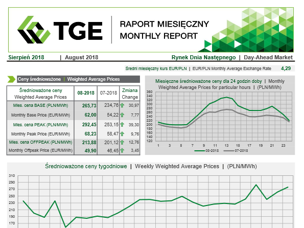


-
ASTRO SEMI 380W - 400W MONO CHSM72M - HC (156,75)
13926 Widoki . -
ASTRO SEMI 370W-380W MONO CHSM60M-HC (166)
9803 Widoki . -
Taryfa TAURON Dystrybucja SA na rok 2018
9118 Widoki . -
PSG taryfa 7 - stawki
9111 Widoki . -
ASTRO TWINS 405W-415W MONO CHSM72M (DG)F-BH (158.75)
8301 Widoki . -
AXPO
8243 Widoki . -
ASTRO SEMI 330W-340W MONO CHSM-HC (158.75)
7793 Widoki . -
Taryfa PGNiG aktualna na 2019
7508 Widoki . -
ASTRO SEMI 400W - 410W MONO CHSM72M - HC (158,75)
7358 Widoki . -
ASTRO SEMI 355W-365W MONO CHSM60M(BL)-HC (166)
7341 Widoki . -
ASTRO SEMI 285W - 300W POLY CHSM60P - HC (156,75)
6925 Widoki . -
Wniosek o nr tech. 62060, ver. 1 - 2019-08-07 130405
6605 Widoki . -
Enea Operator Taryfa na rok 2019
6512 Widoki . -
ASTRO SEMI 445W-455W MONO CHSM72M-HC (166)
6415 Widoki . -
Taryfa 2018 ENERGA OPERATOR SA
6061 Widoki . -
Rozwój_OZE_w_sektorze_MSP
5998 Widoki . -
ASTRO NOVA 270W - 280W POLY CHSM6610P -HV (156,75)
5930 Widoki . -
-
2018 06 Cennik Gaz dla Biznesu PGNiG OD
5889 Widoki . -
zal_1_lista_wymaganych_zalacznikow_agroenergia
5712 Widoki .